Programming Finder OPTA via Ethernet in CODESYS
Guide and Tutorial | Programming Finder OPTA via Ethernet in CODESYS
Programming Finder OPTA via Ethernet in CODESYS
Overview
CODESYS is one of the leading development environments for PLCs and allows you to program Finder OPTA using standard languages such as LD and ST.
This tutorial will guide you through programming Finder OPTA in just a few simple steps.
Goals
- Configure the Ethernet network to communicate with Finder OPTA
- Upload a program to Finder OPTA via Ethernet
Requirements
Before you begin, make sure you have:
- Finder OPTA PLC CODESYS (×1)
- 12 W or 25 W switching power supply for OPTA (×1)
- Ethernet cable (×1)
- CODESYS development environment installed with the OPTA Configurator plug-in. See the installation guide here
Instructions
The Finder OPTA is preset with the IP address 10.0.0.2 and the subnet mask 255.255.255.0. Therefore, your PC must be assigned an address on the same network. In the tutorial, the address 10.0.0.1 with mask 255.255.255.0 is used, but this is just an example: you can choose any address within the range defined by the subnet.
Setting the PC’s IP Address
To change your Windows PC’s IP address, open Settings and go to Network & Internet:

Select Ethernet:
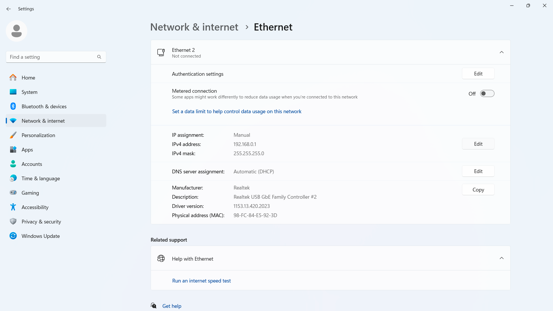
Click Edit:

Replace the existing address with 10.0.0.1:
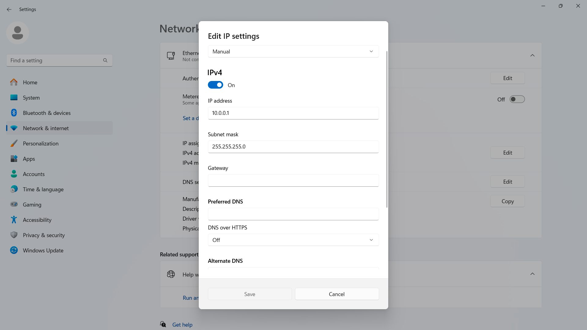
Save and exit the edit screen.
Uploading a Program to Finder OPTA via Ethernet
Power the Finder OPTA with the switching power supply, then connect it to your PC using the newly configured IP.
Creating a CODESYS Project
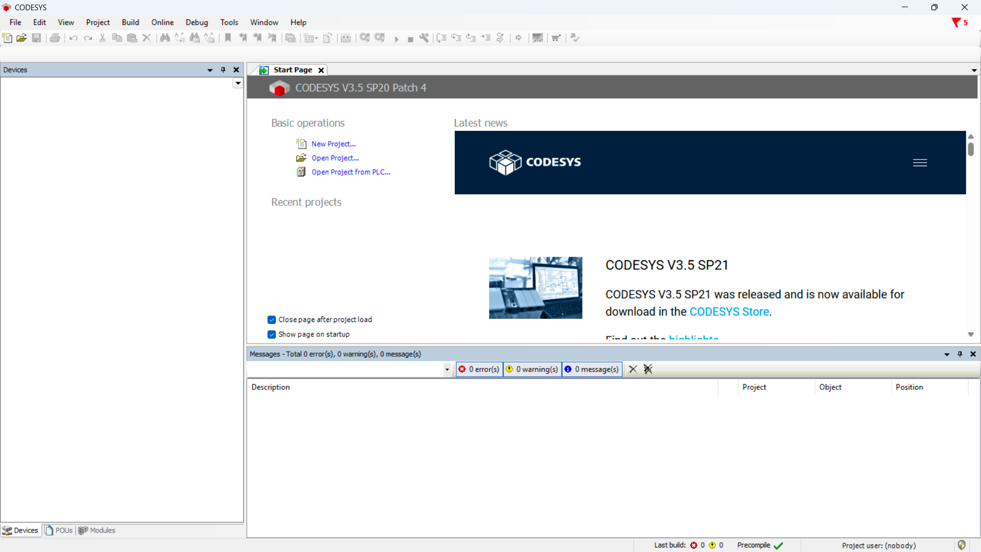
Open CODESYS:
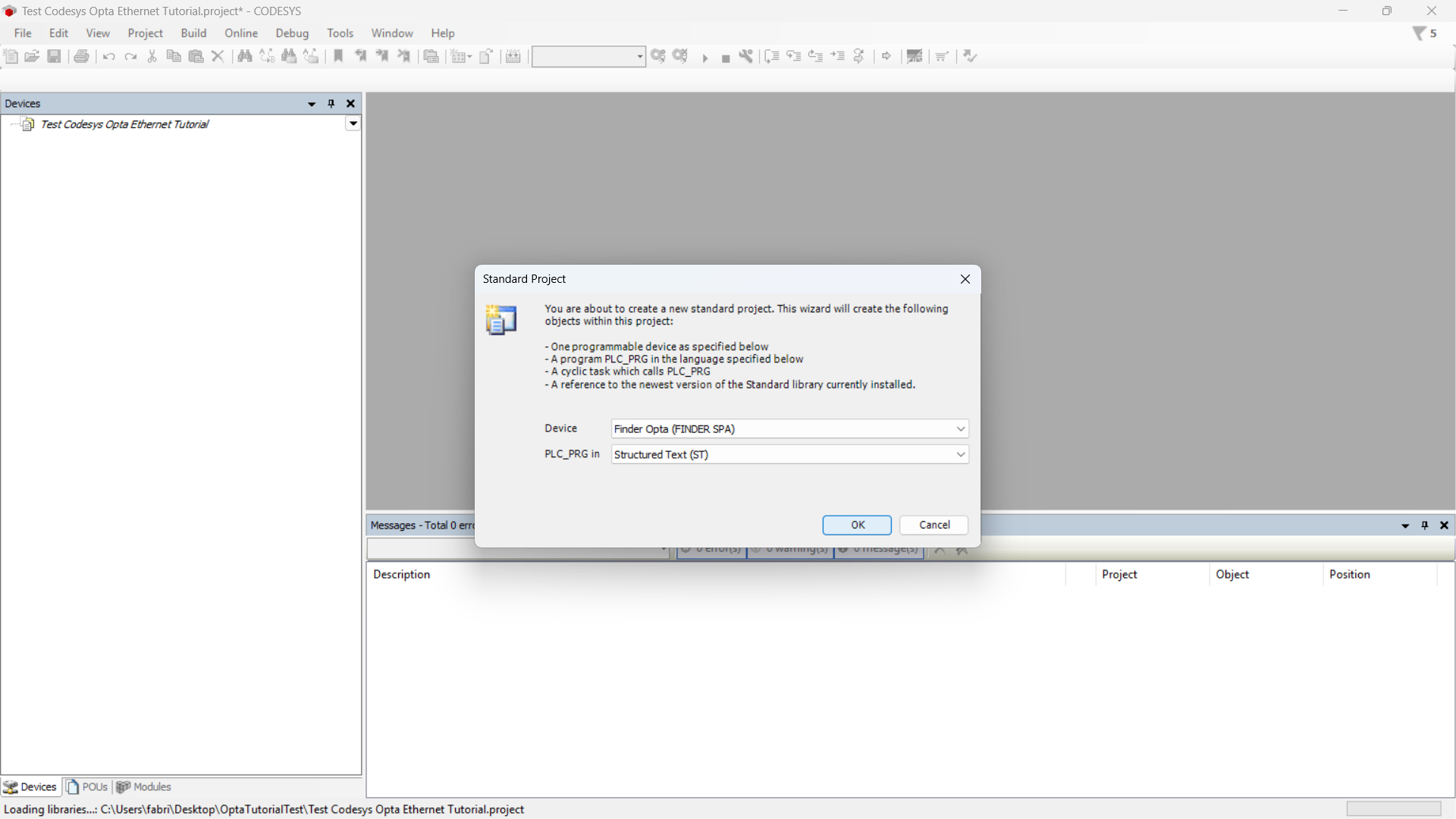
Create a new project and choose Standard Project:
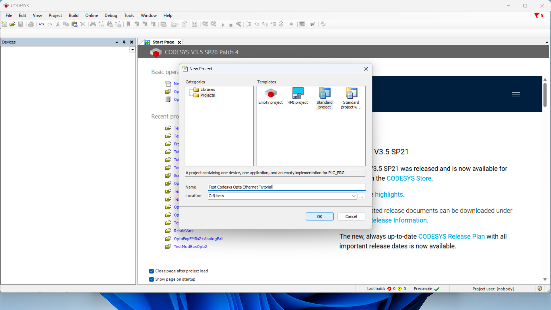
Ensure the device is Finder OPTA, then select your programming language:
Detecting Finder OPTA over Ethernet
Now double-click Device (Finder OPTA) in the Devices tree; a pane like this will open:
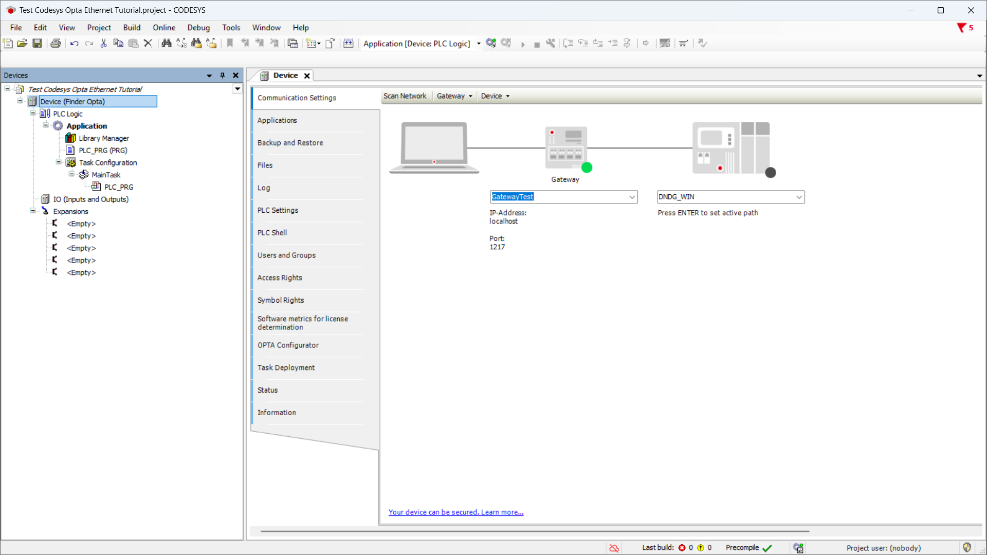
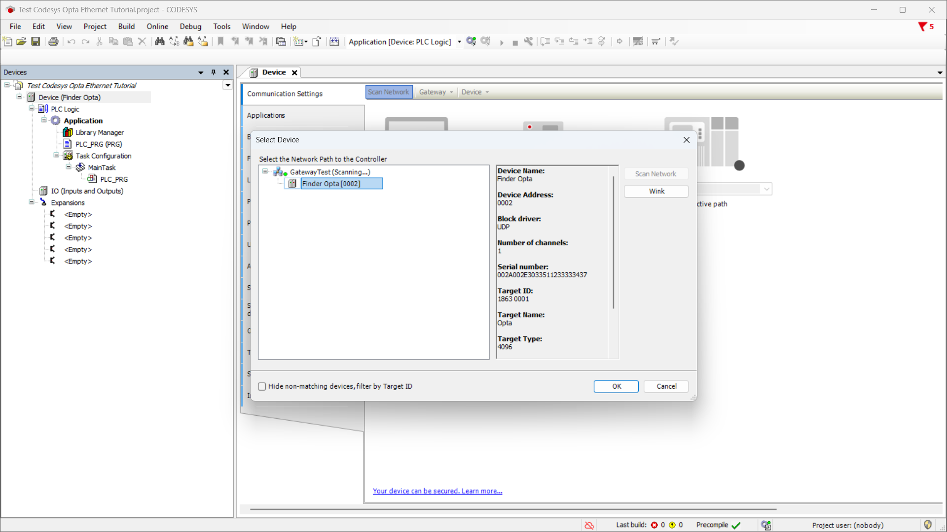
Click Scan Network and confirm you see the Finder OPTA device appear under the Gateway:
ST Program Setup
If you already have an ST program to upload to OPTA, skip the next steps and go directly to Uploading the Program to Finder OPTA.
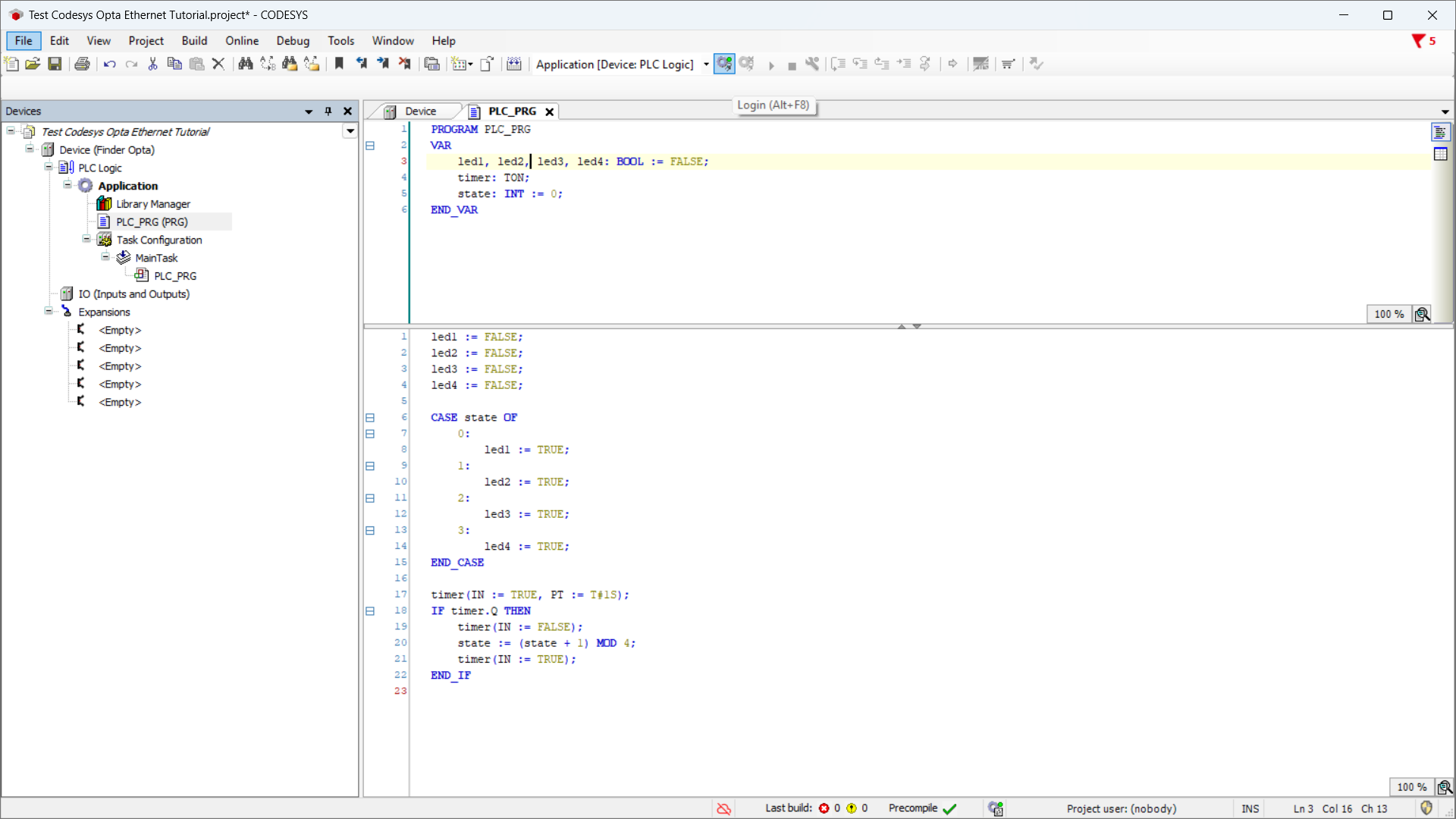
Double-click the program name under Devices (here it’s PLC_PRG (PRG)):
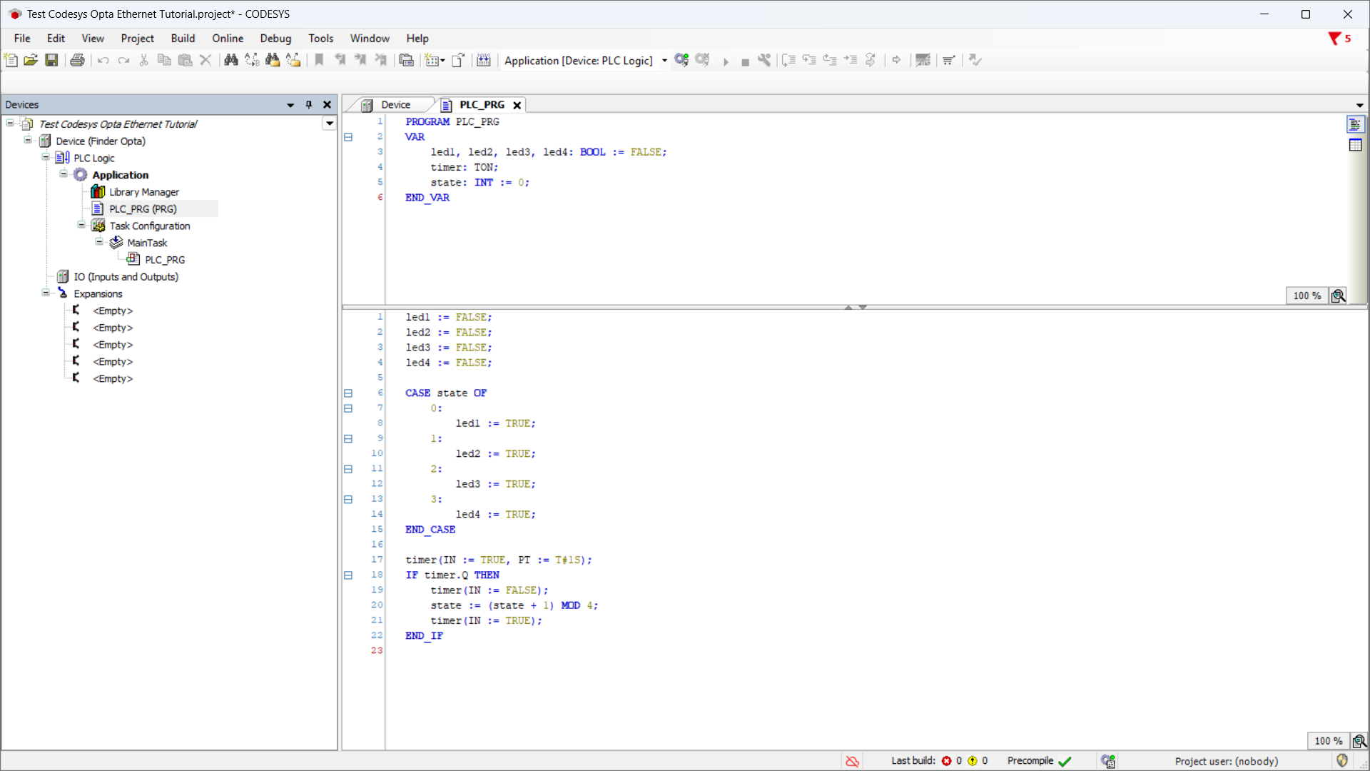
Copy the following ST code:
PROGRAM PLC_PRG
VAR
    led1, led2, led3, led4: BOOL := FALSE;
    timer: TON;
    state: INT := 0;
END_VAR

led1 := FALSE;
led2 := FALSE;
led3 := FALSE;
led4 := FALSE;

CASE state OF
    0:
        led1 := TRUE;
    1:
        led2 := TRUE;
    2:
        led3 := TRUE;
    3:
        led4 := TRUE;
END_CASE

timer(IN := TRUE, PT := T#1S);
IF timer.Q THEN
    timer(IN := FALSE);
    state := (state + 1) MOD 4;
    timer(IN := TRUE);
END_IF
Next, double-click I/O under Devices, then select Opta I/O Mapping:
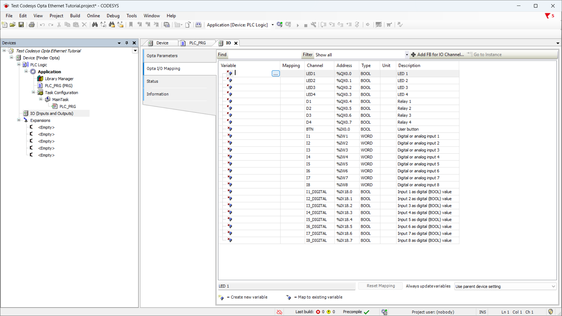
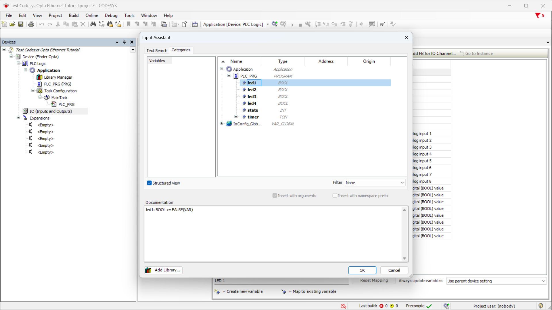
Double-click a variable cell to show the options button, click it, expand Application, then expand your program name to reveal the LED variables:
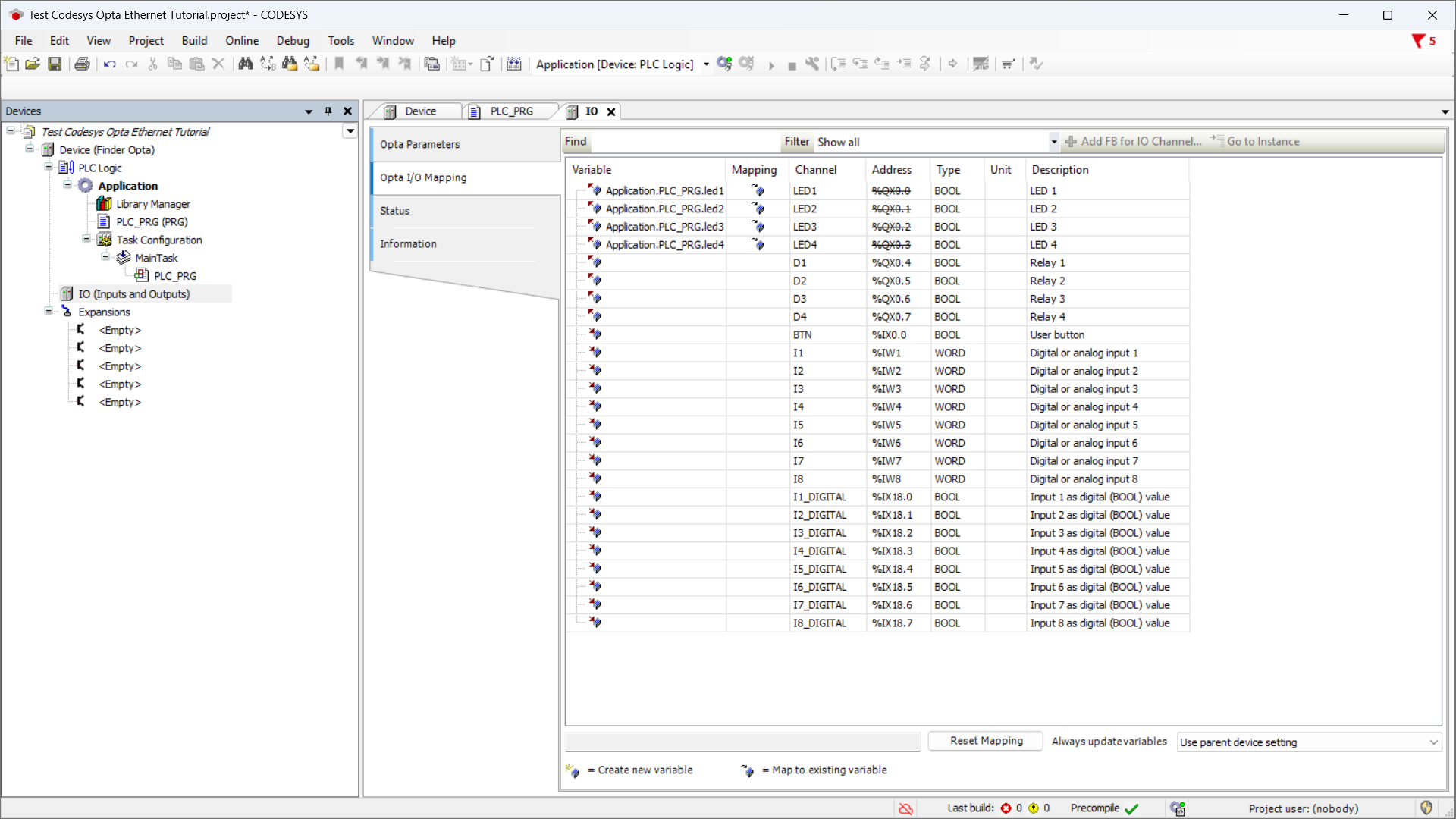
Map each LED to its corresponding variable until it looks like this:
Uploading the Program to Finder OPTA
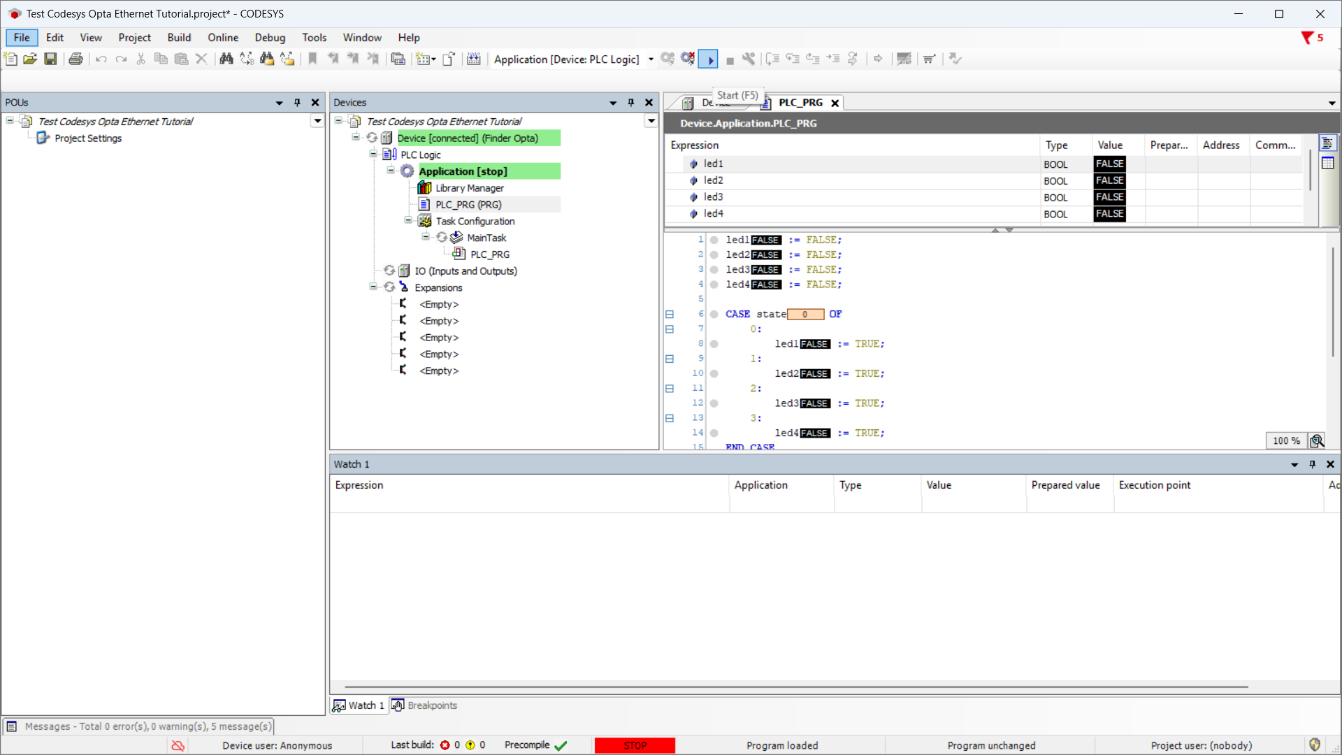
Now upload the program by clicking the green Login button at the top:
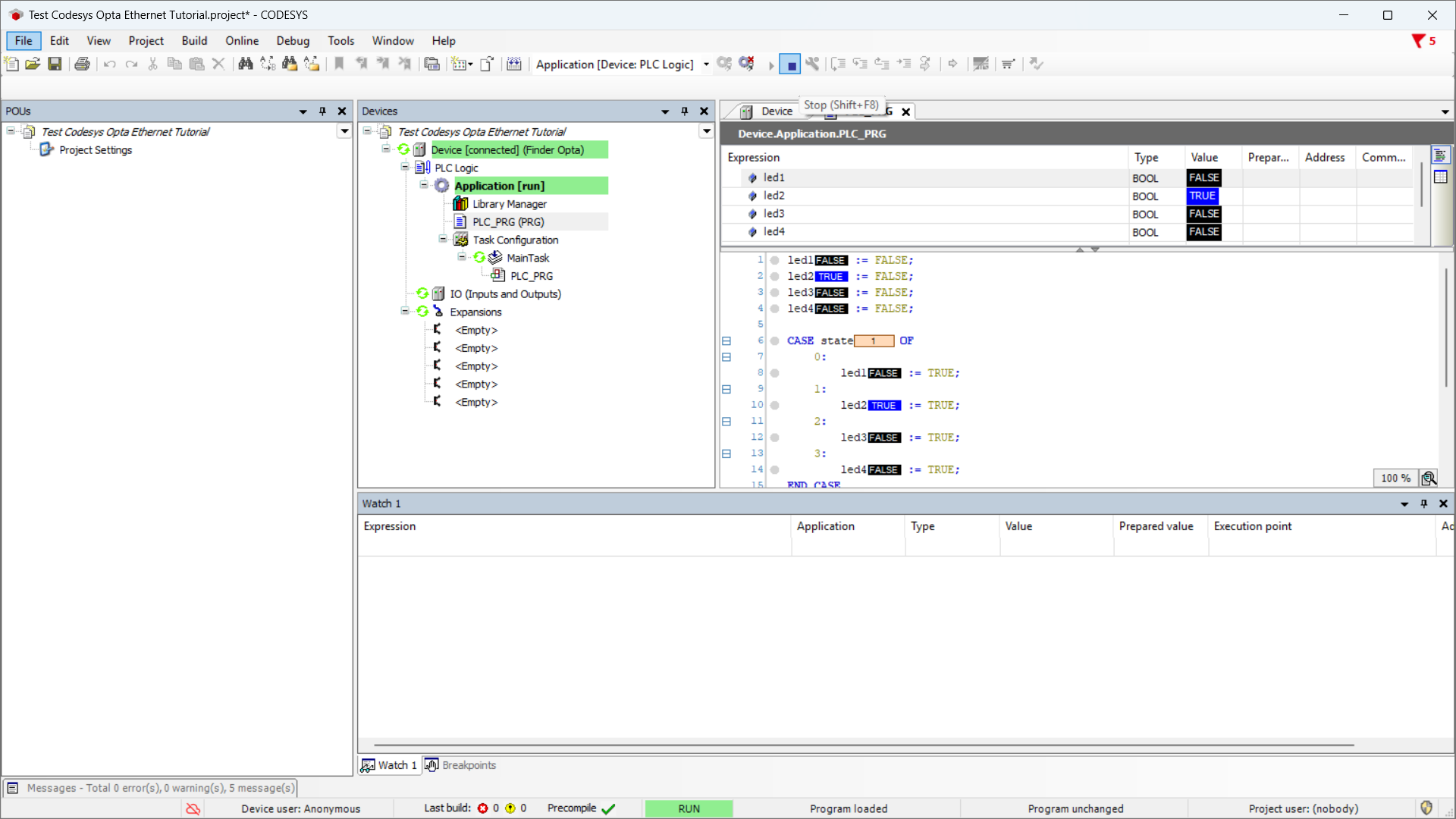
After it loads, press Start to run the program:
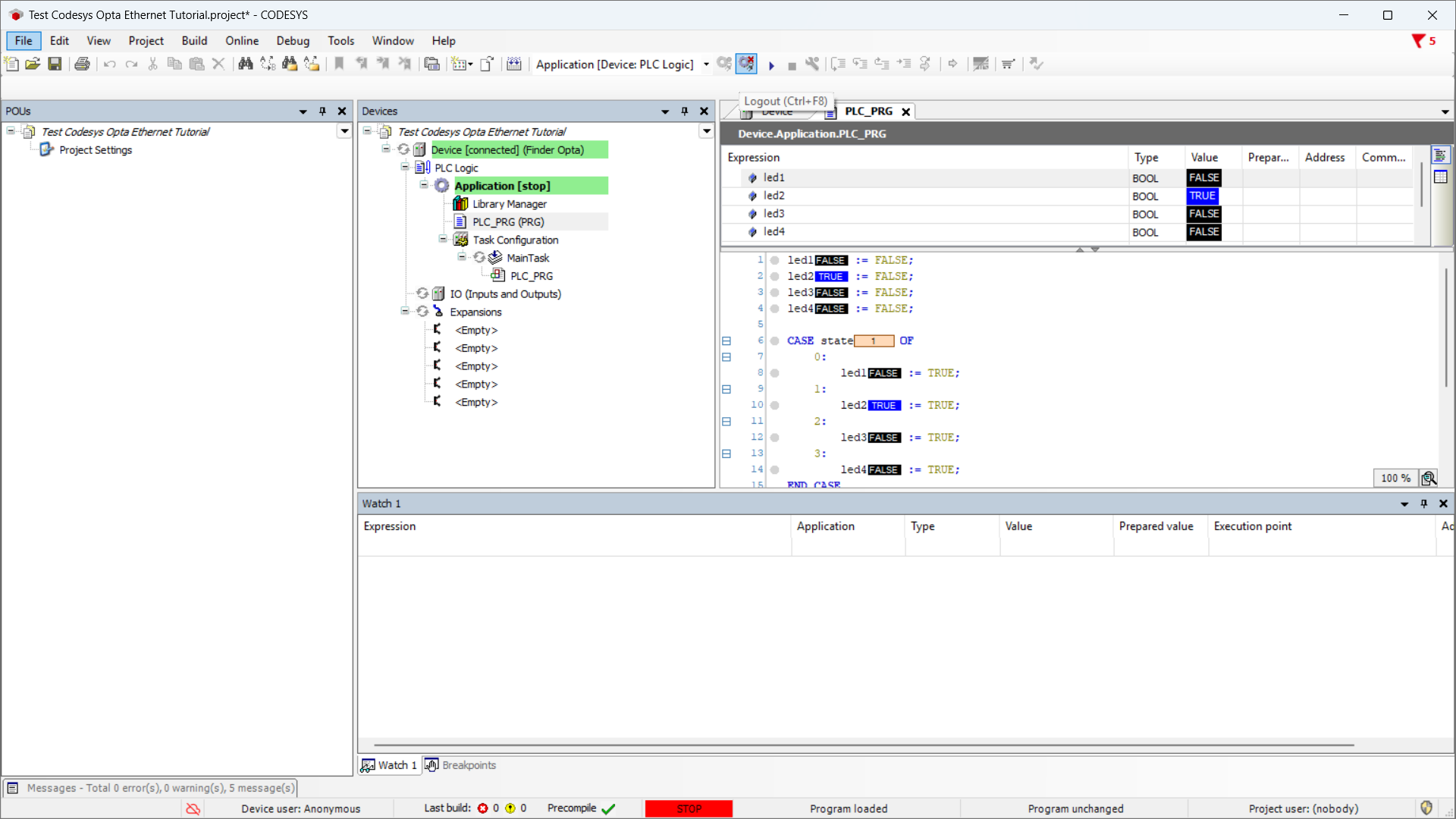
The program will start, and the four LEDs on OPTA will begin cycling on and off. To stop it, click Stop:
Finally, disconnect by clicking Logout:
Conclusions
By following these steps, you have successfully programmed Finder OPTA in CODESYS via Ethernet and verified that the device is correctly connected to the network.
If you encounter any issues during setup, make sure you followed each step carefully.