Introduction to Programming in PLC IDE with Finder OPTA
Guide and Tutorial | Introduction to Programming in PLC IDE with Finder OPTA
Introduction to Programming in PLC IDE with Finder OPTA
Guide to get started programming Finder OPTA in Arduino PLC IDE.
Overview
This tutorial offers an introduction to PLC programming in Arduino PLC IDE with Finder OPTA. Within this guide, you will discover which programming languages are compatible with Arduino PLC IDE and how to use them effectively.
What You Will Need
Before starting, make sure you have:
- Finder OPTA PLC (x1)
- USB-C cable (x1)
- Arduino PLC IDE correctly installed on your computer.
If you have not yet activated the license for the Finder OPTA device, follow this guide to complete the activation.
This tutorial assumes you are already familiar with some basic concepts covered in the guide “First Steps with Finder OPTA and PLC IDE”. If you have not yet consulted it, we recommend doing so before proceeding: it will provide the necessary foundation to better understand the steps described below.
The IEC-61131-3 Standard
The IEC-61131-3 standard defines a framework for PLC programming, allowing developers to write code in a uniform format, regardless of the hardware manufacturer.
IEC-61131-3 includes five programming languages that can be used individually or combined within the same project:
- Structured Text (ST)
- Instruction List (IL)
- Ladder Diagram (LD)
- Sequential Function Chart (SFC)
- Functional Block Diagram (FBD)
Arduino PLC IDE supports all these languages, allowing them to be combined in the same project and interact using shared variables.
We will see practical examples for each language type, implementing the same counter function in each language. Before doing that, we need to create the variables that we will use to implement the counter.
Preparing Variables and Watch
In this tutorial, we will use global variables so that we don't have to recreate them for each language. If you want to learn more about global and local variables, follow this guide.
For the counter function, we will use two variables: one to serve as the counter that accumulates the count value, and the other to serve as a constant increment:
- cnt: variable with initial value
0, used to hold the updated counter value. - addition: variable with initial value
1; the Attribute field must be set to CONSTANT to indicate that the value is constant.
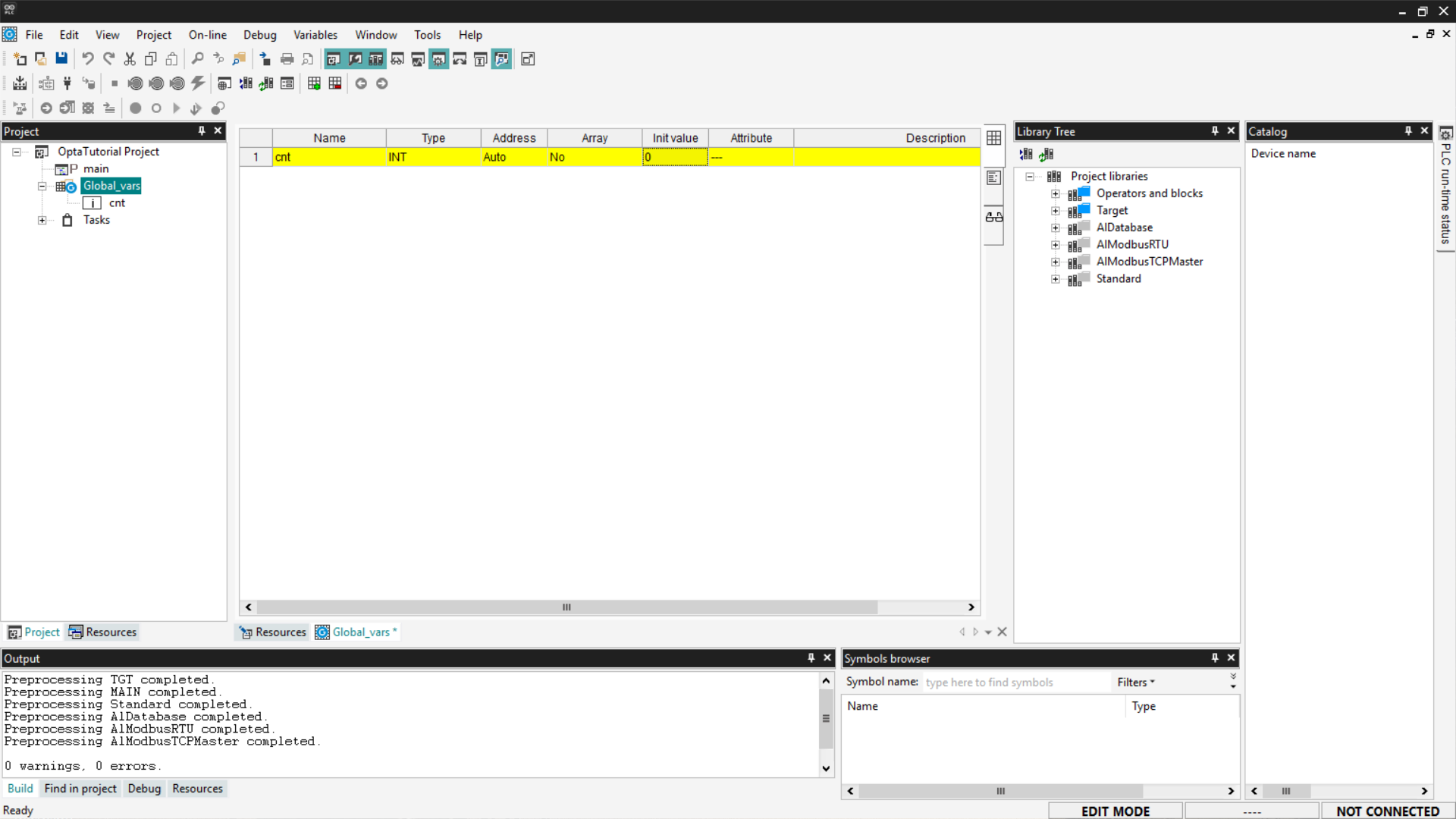
To add the variables, go to Project > Global_vars. Set the initial value of the cnt variable to 0 by clicking on the corresponding field.
To insert a new variable, right-click and select on Insert.
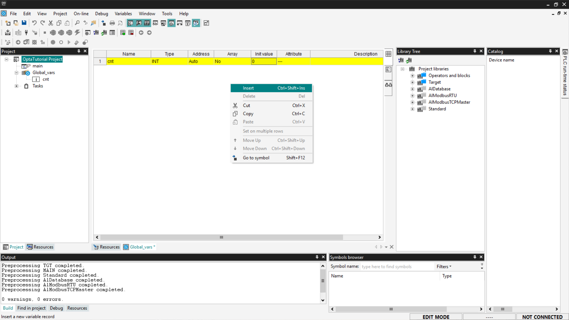
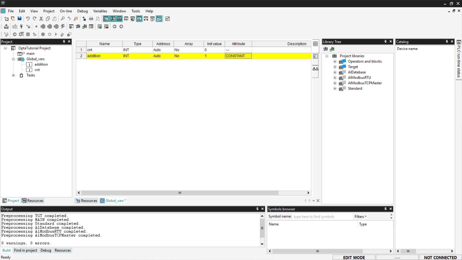
A new row will appear in the table; modify the following values:
- Name:
addition. - Type:
INT, it must be of integer type. - Init Value:
1. - Attribute:
CONSTANT, indicates that the value is constant.
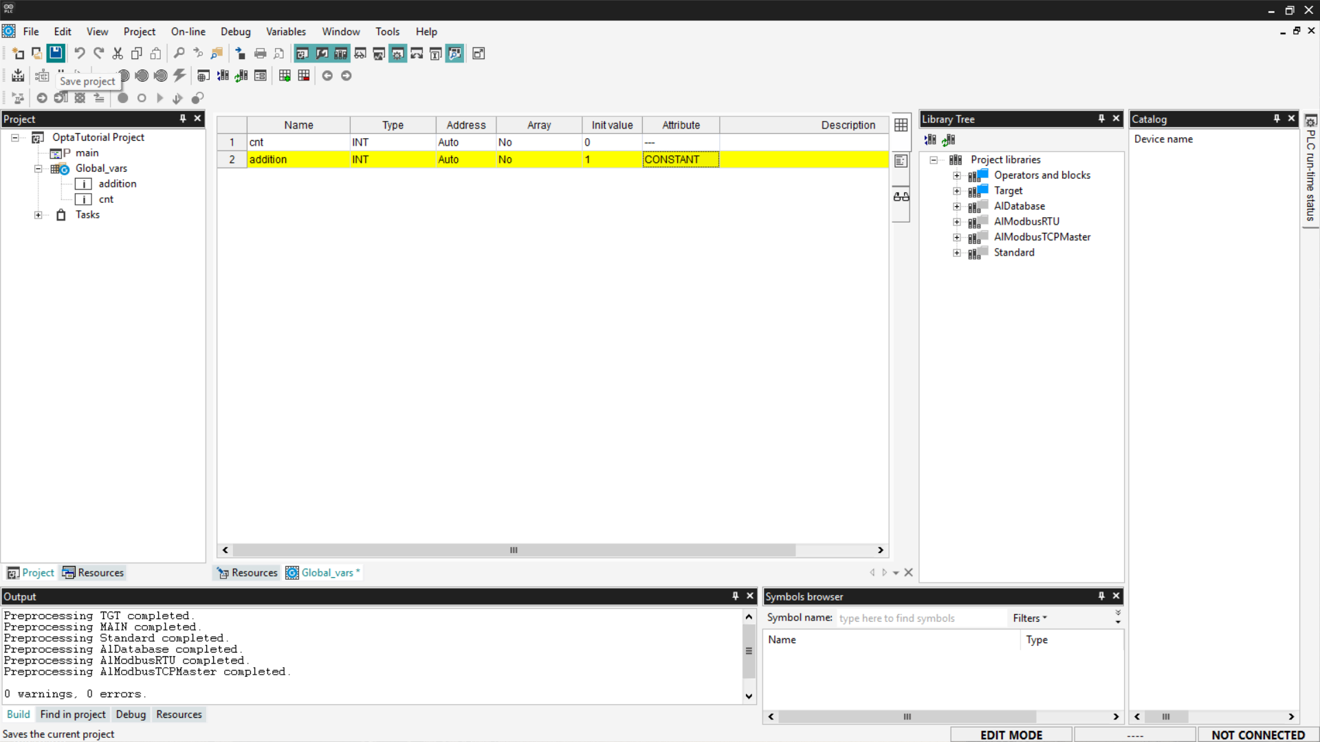
At this point, save your changes by clicking the Save button at the top left.
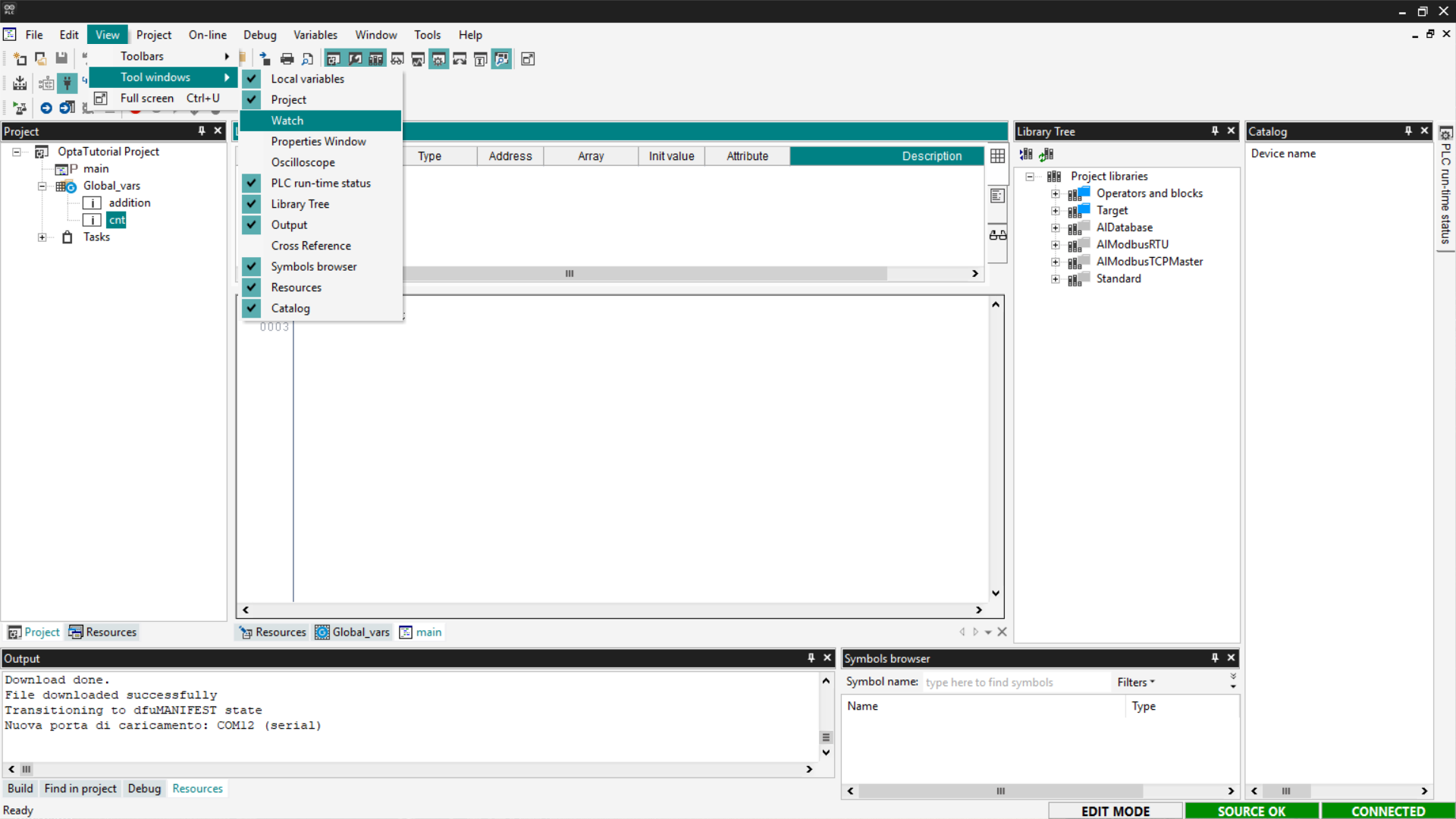
To monitor the counter variable and understand if its value is increasing, we need to prepare the Watch. If you want more information about this tool, follow this guide.
Show the Watch section by selecting View > Tool Windows > Watch.
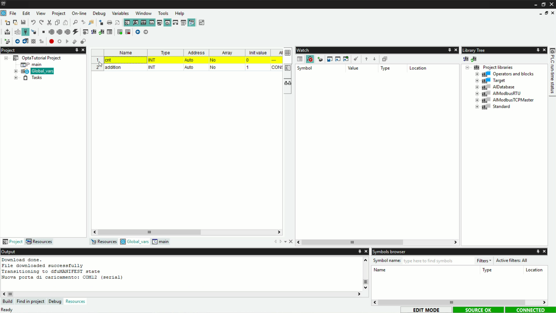
To add the variable to the Watch, drag the cnt element from the list of global variables into the Watch area.
Alternatively, click on Insert New Item and choose the cnt variable from the list of proposed variables.
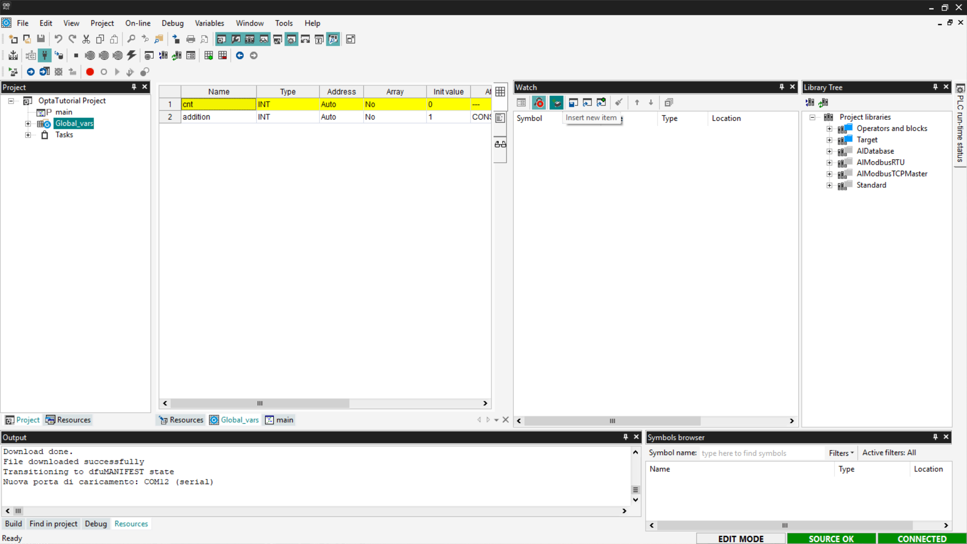
This way, we will have the Watch ready to monitor the cnt variable and check if the programs downloaded to Finder OPTA are working.
Structured Text (ST)
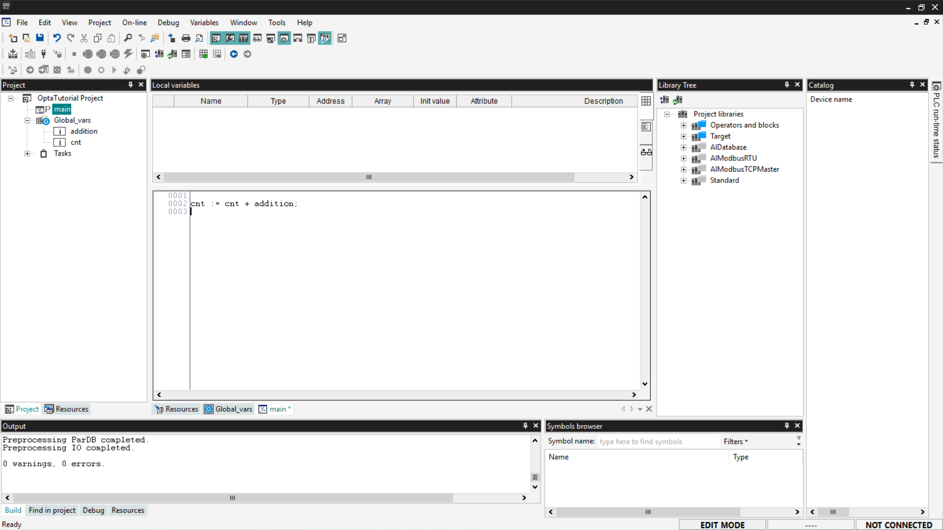
Structured Text (ST) is a textual programming language similar to C, designed to implement complex logic in a readable and structured way. The code that implements a counter in ST is as follows:
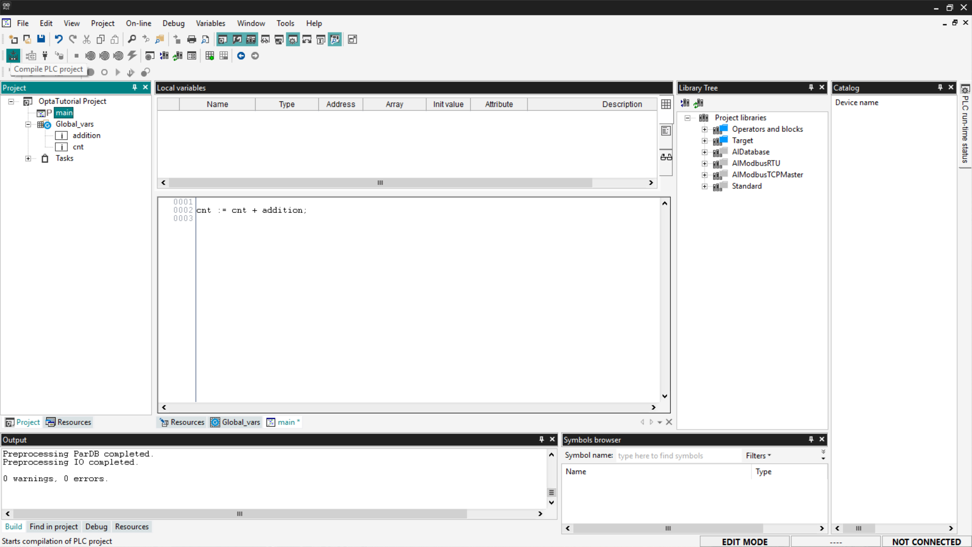
cnt := cnt + addition;This instruction updates the cnt variable by adding a constant (or variable) addition to its current value. Copy the code and paste it into the main entry in the tree menu under the Project section.
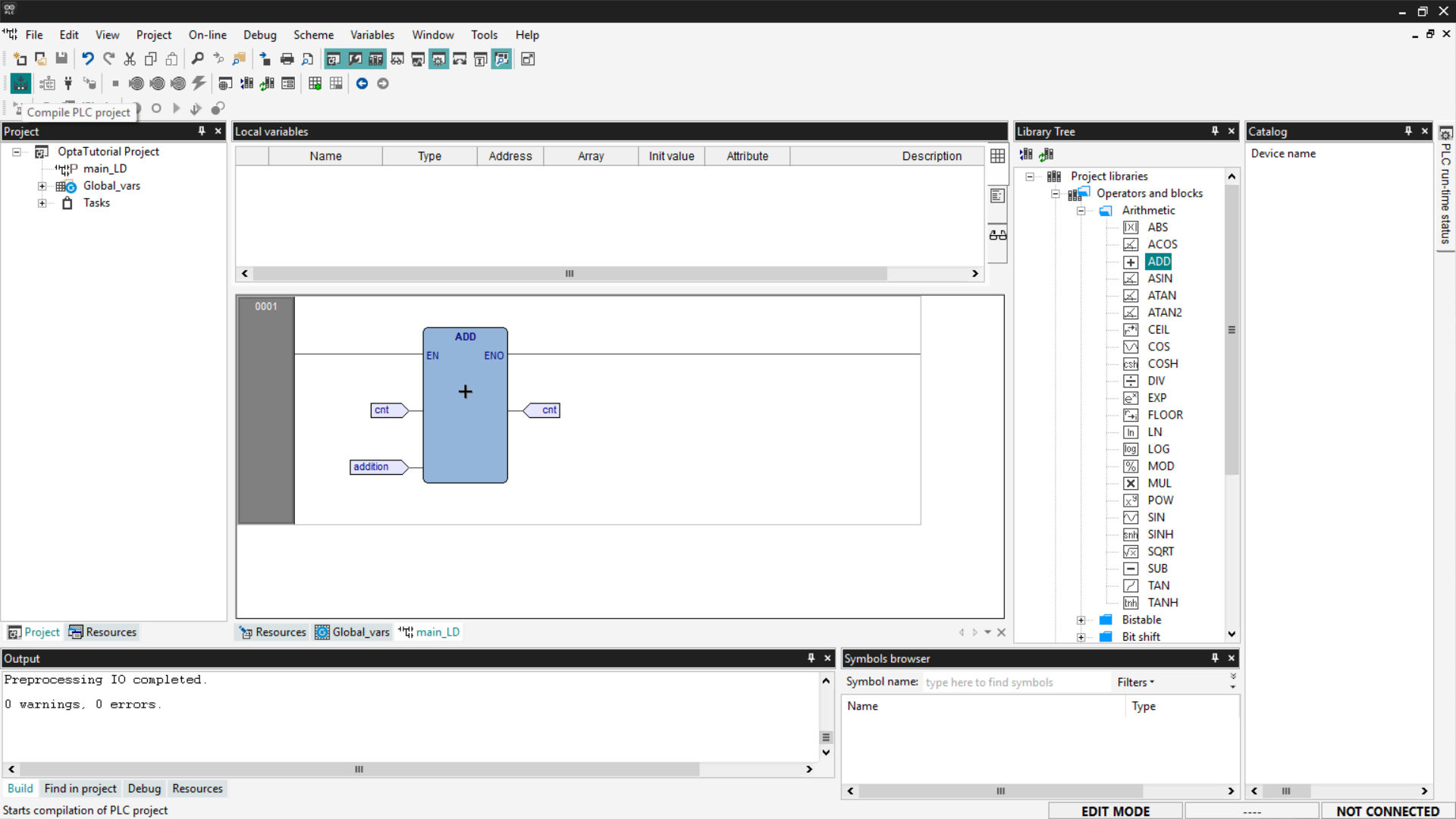
Next, compile the code using the Compile PLC project button at the top left.
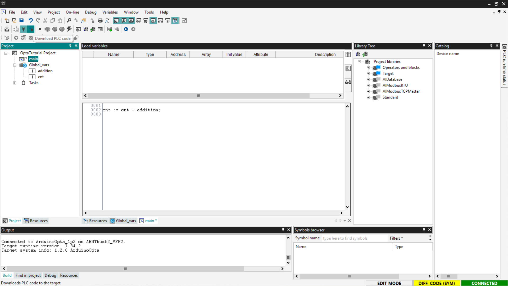
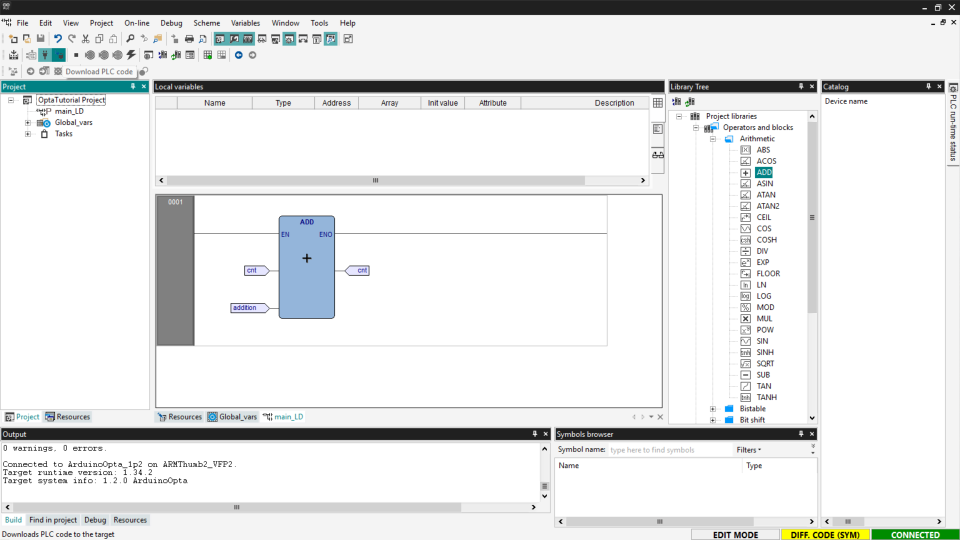
Now connect to the device and download the code to Finder OPTA by clicking the Download PLC code button.
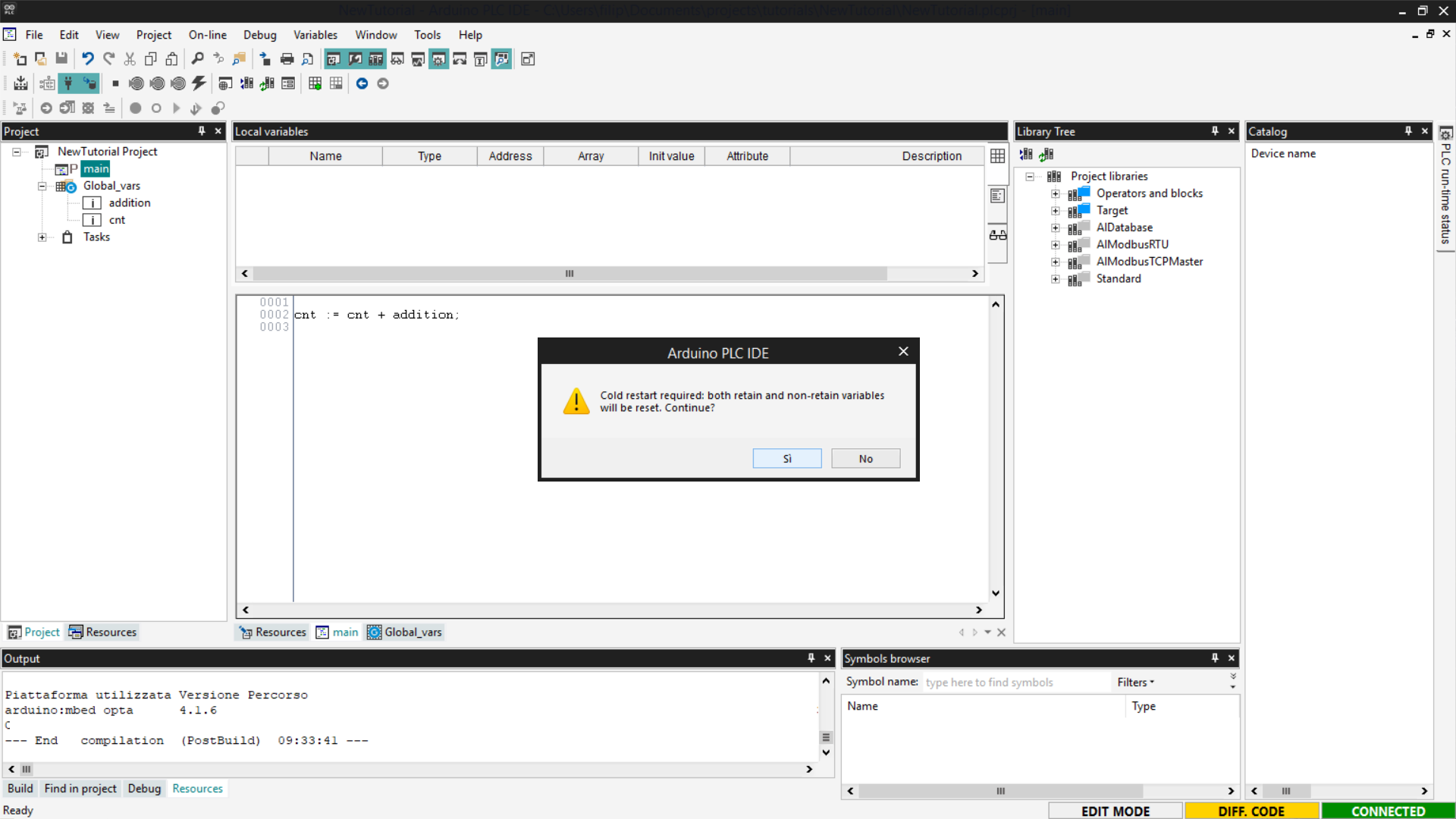
You will be asked if you want to proceed with resetting the variables; click Yes to confirm.
Open the Watch window to verify that the counter value is increasing correctly. If the value is not visible, click on Start/Stop Watch.
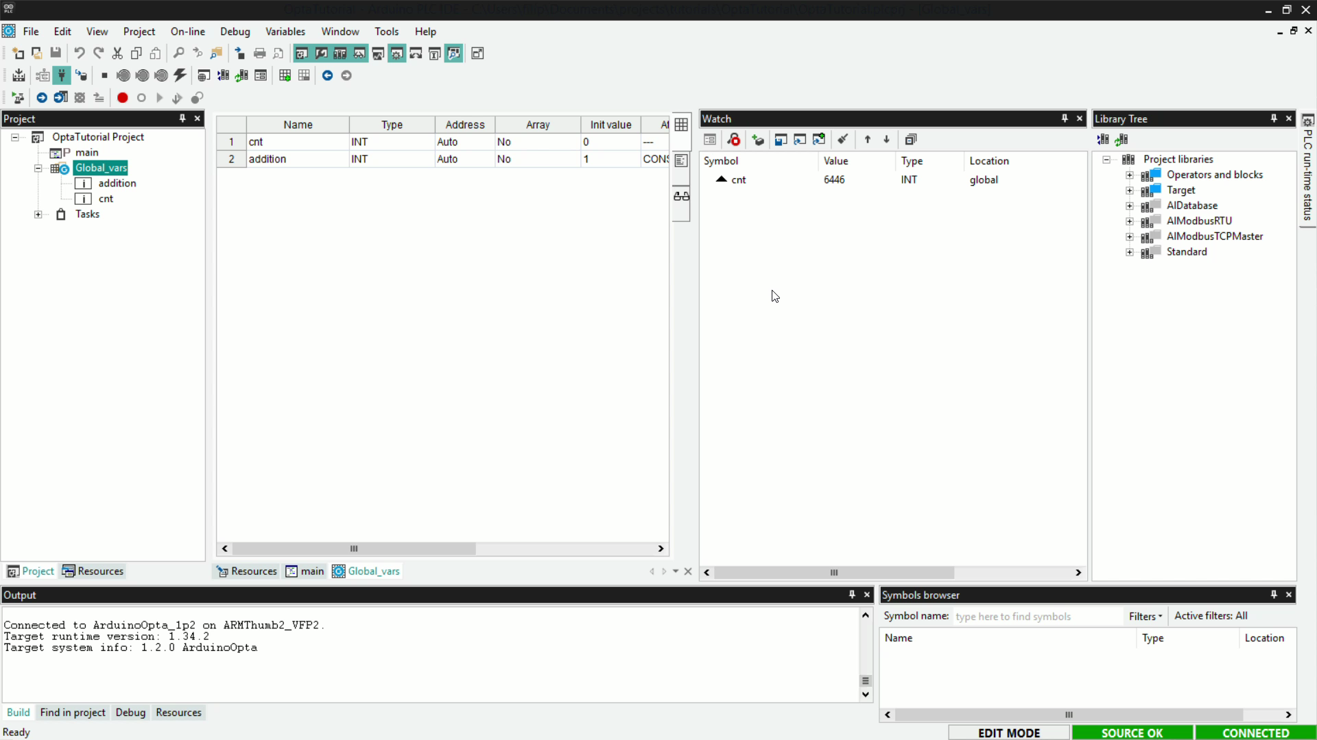
If the value of cnt increments, it means that the counting program written in ST has been loaded correctly onto Finder OPTA and is running without errors.
Instruction List (IL)
Instruction List (IL) is a compact textual programming language, similar to Assembly. It is particularly suitable for sequential operations and simple logic, using direct commands and linear syntax.
An example of a counter in IL is as follows:
LD cnt
ADD addition
ST cnt
In detail:
LD cntloads the value of the cnt variable onto the logic unit’s stack.ADD additionadds to this value the value of the addition variable.ST cntstores the result back into the cnt variable.
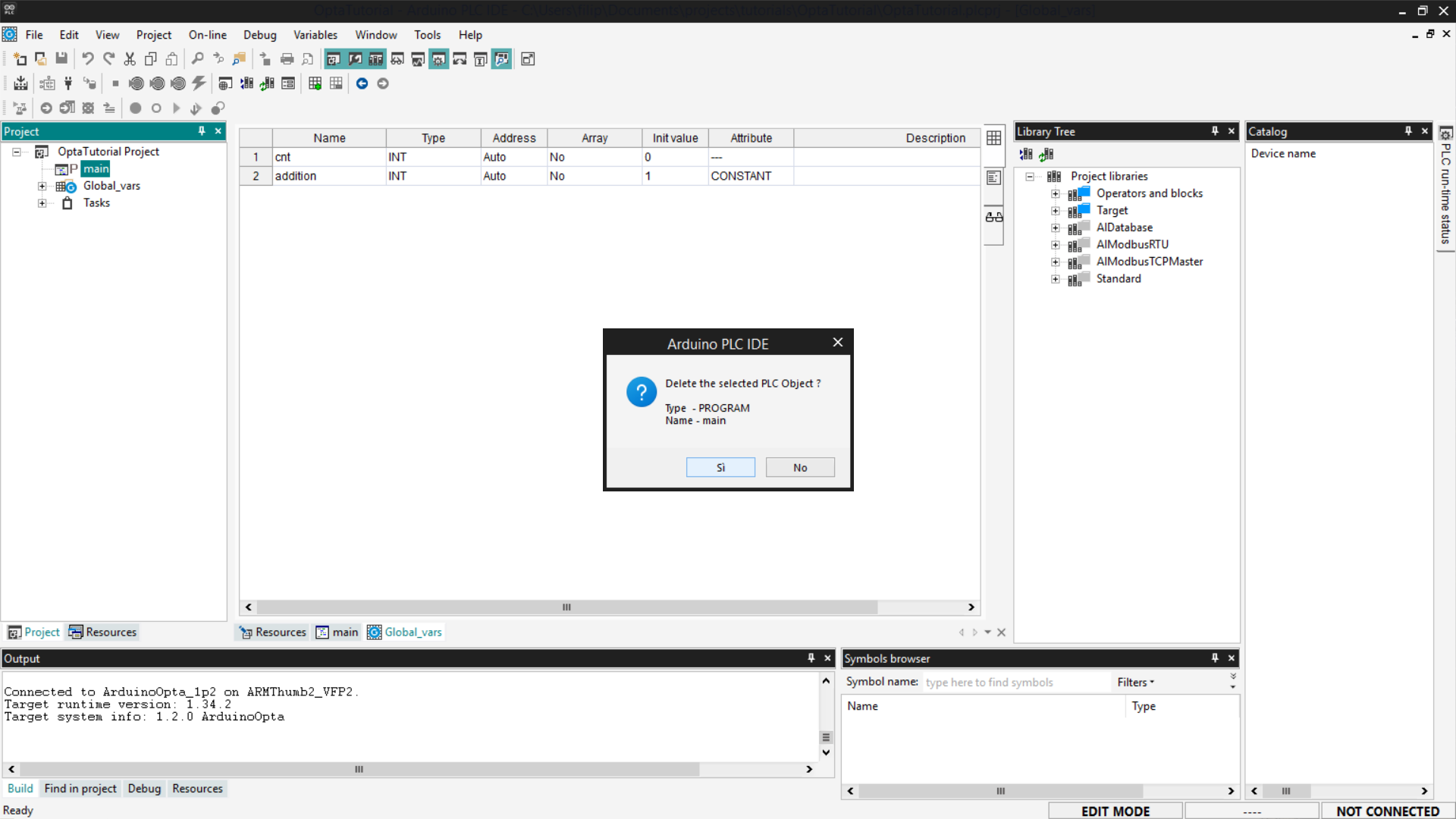
Before proceeding, delete the previous program to avoid conflicts with global variables: right-click on the previously created program and select Delete program.
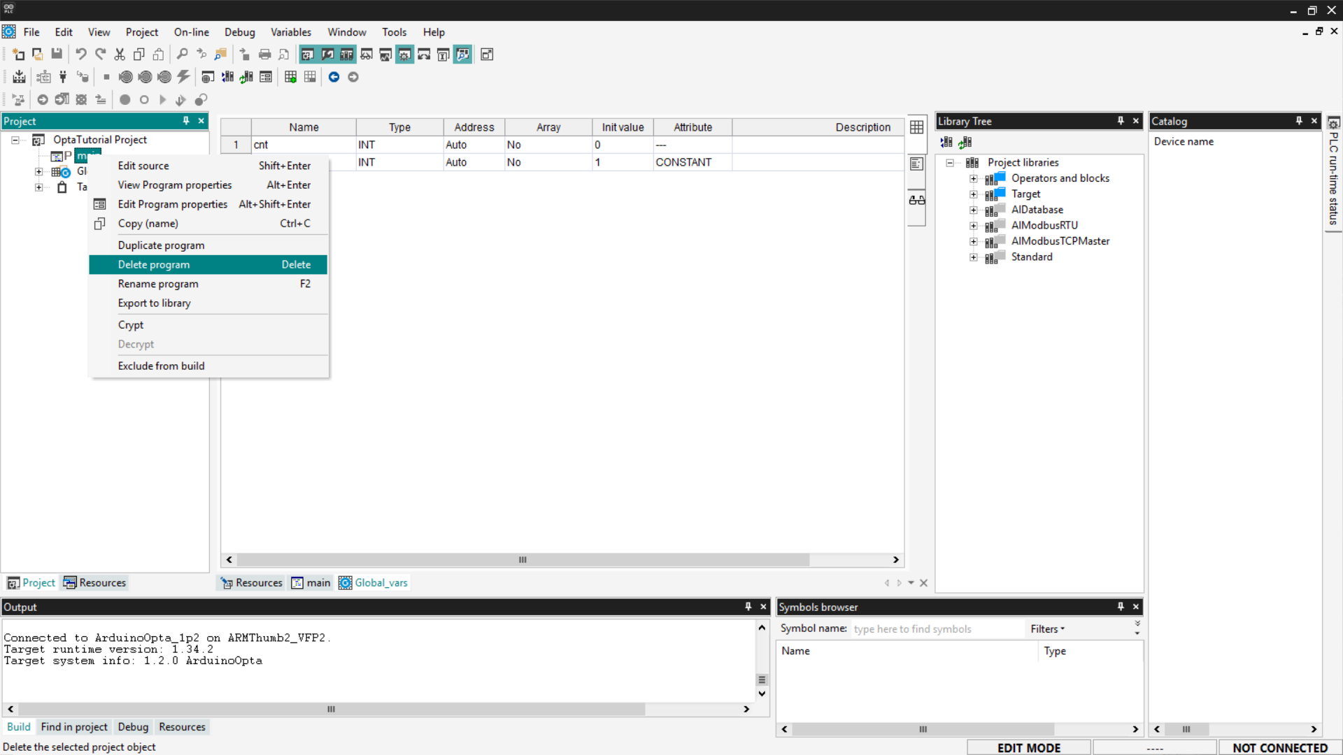
You will be asked to confirm the deletion; click Yes.
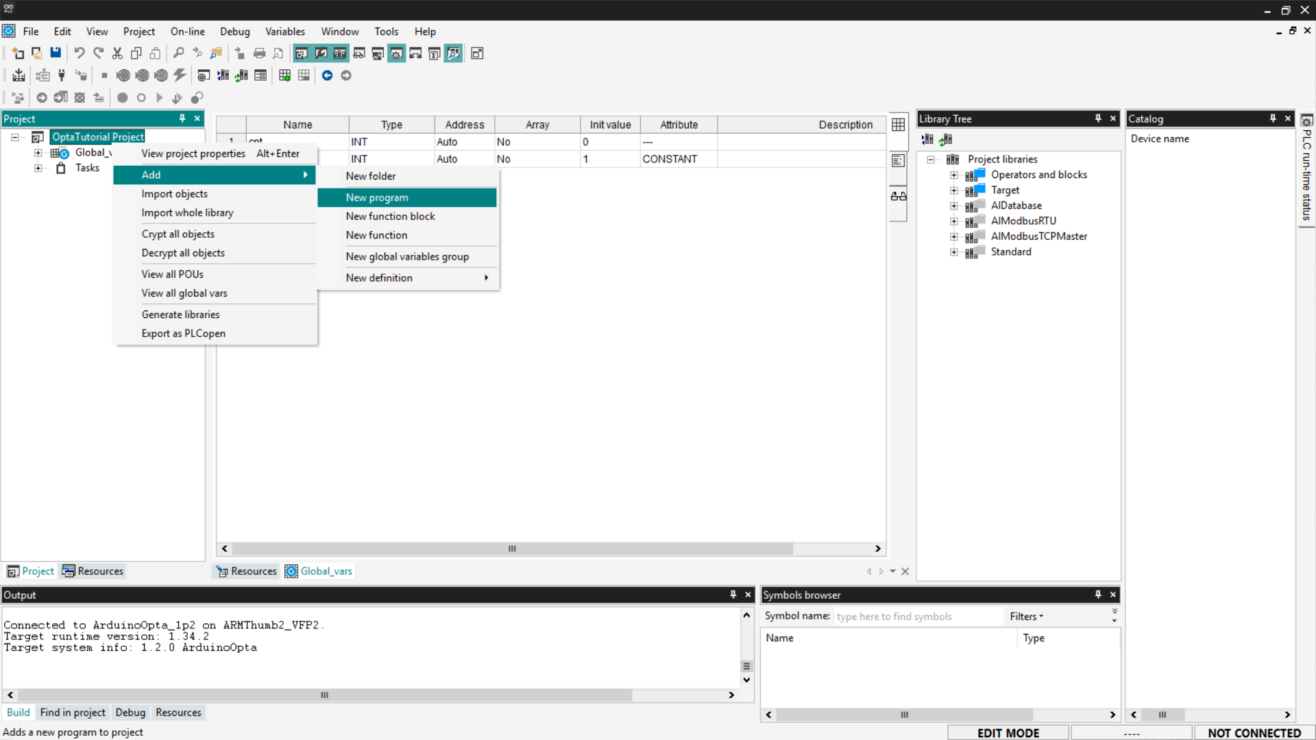
Now add the new IL program: right-click on the project name and select Add > New Program.
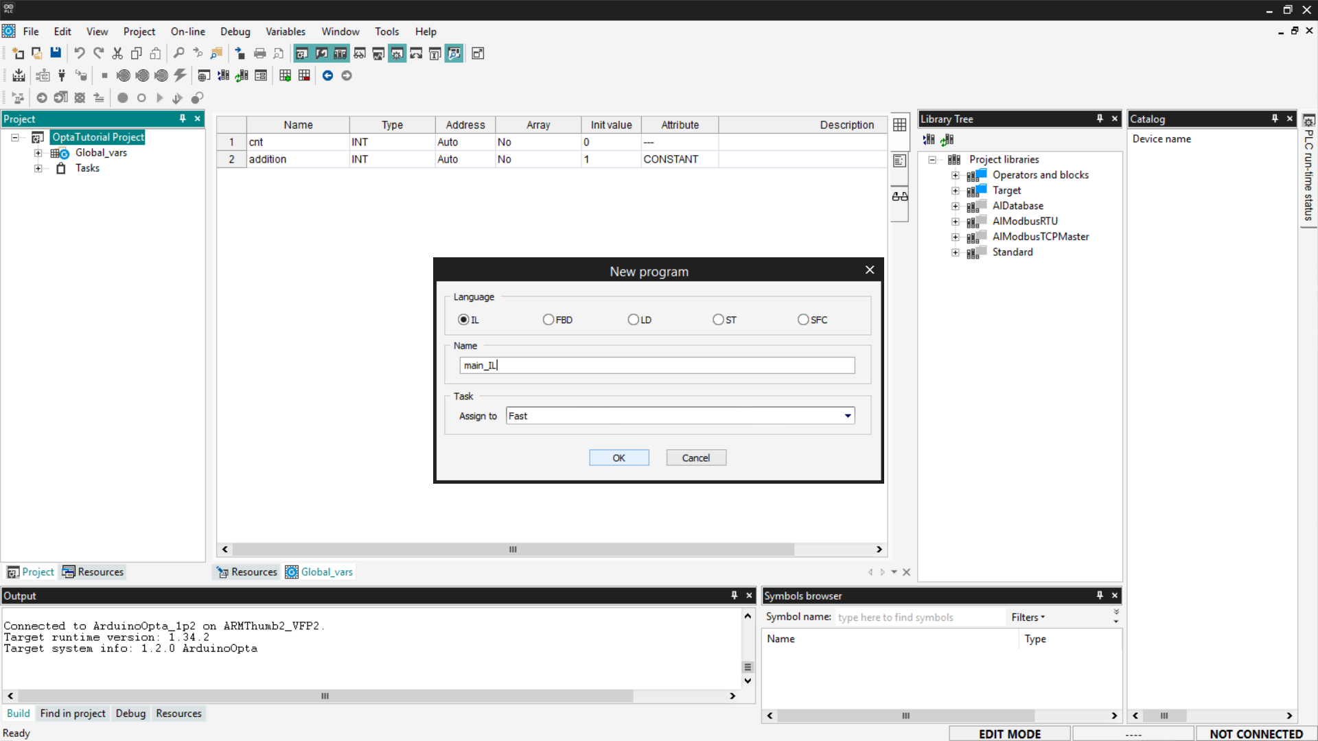
Set the language to IL and assign the program to the Fast task type to increase the program’s execution frequency. If you want to know more about how tasks work, follow the guide “First Steps with Finder OPTA and PLC IDE”.
Copy the previous code and insert it into the main_IL entry in the tree menu under the Project section.
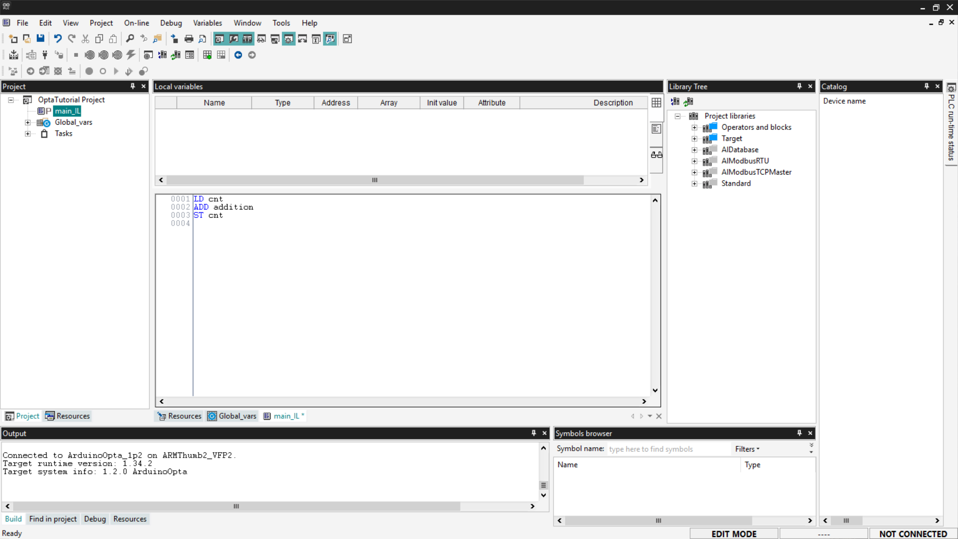
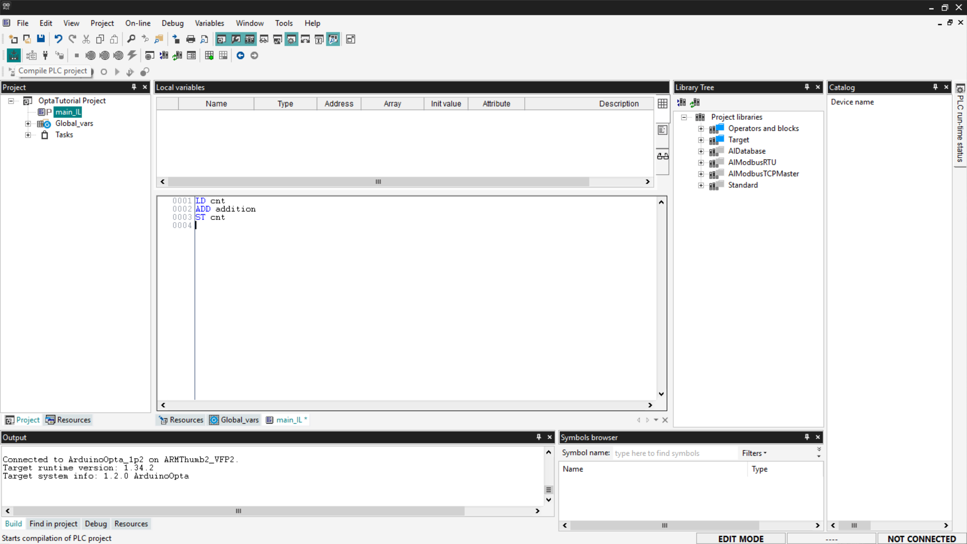
Now compile the program by clicking the Compile PLC project button at the top left.
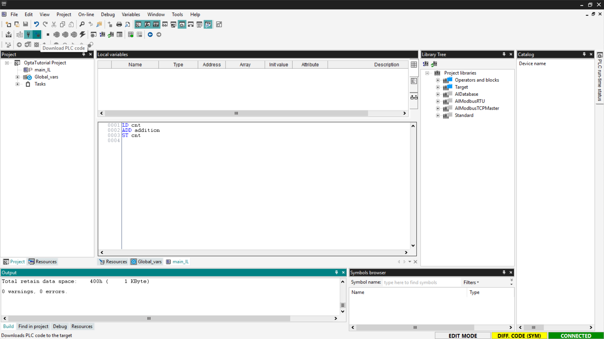
Connect to Finder OPTA and download the program to the PLC by clicking the Download PLC code button.
At this point, the program is running on Finder OPTA; check the Watch as done previously and verify that the value of cnt is increasing.
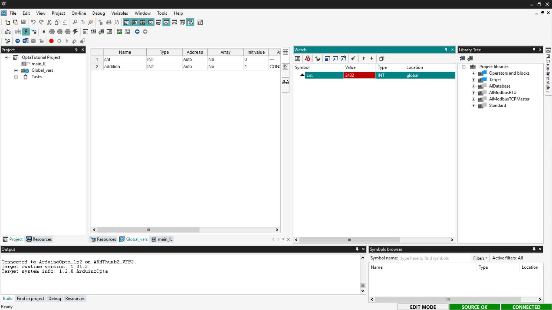
If the counter updates as expected, the IL program has been loaded and executed correctly on Finder OPTA.
Ladder Diagram (LD)
Ladder Diagram (LD) is a programming language based on lines and blocks, used to represent control logic visually.
In a Ladder Diagram, each line represents a virtual current flow that moves from left to right. The flow must pass through all intermediate blocks, such as logic gates (AND, OR), before reaching the right side, where a coil is located.
If the flow successfully passes through all intermediate blocks, the coil is energized, executing the associated action, such as closing a Normally-Open (NO) contact or activating a relay.
In our case, to write a simple counting function, the contact and coil components are not needed. We will use an ADD block to which we will connect the operand variables and the result variable.
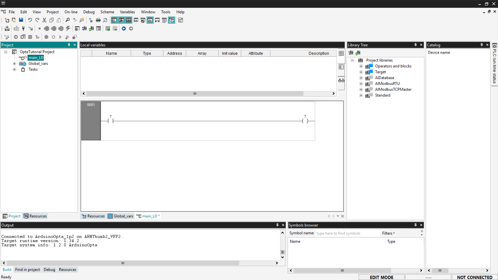
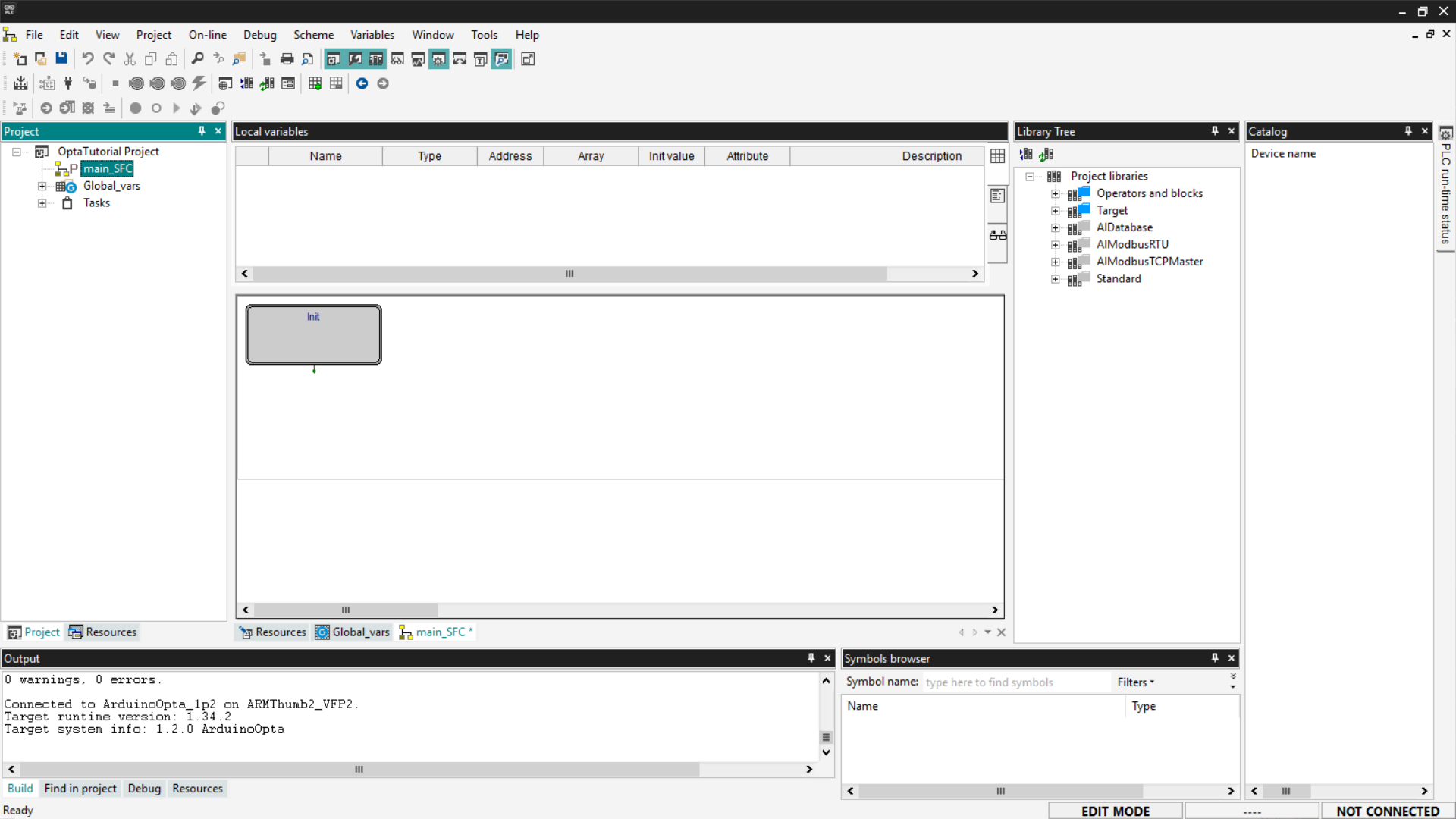
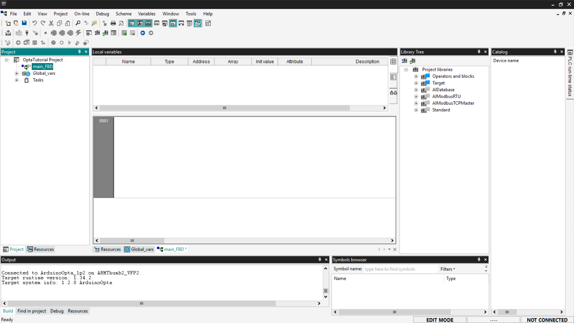
First, delete the previously created programs as shown above and create a new one in LD language, assigning it to a Fast task type. The new program will appear as shown in the following image.
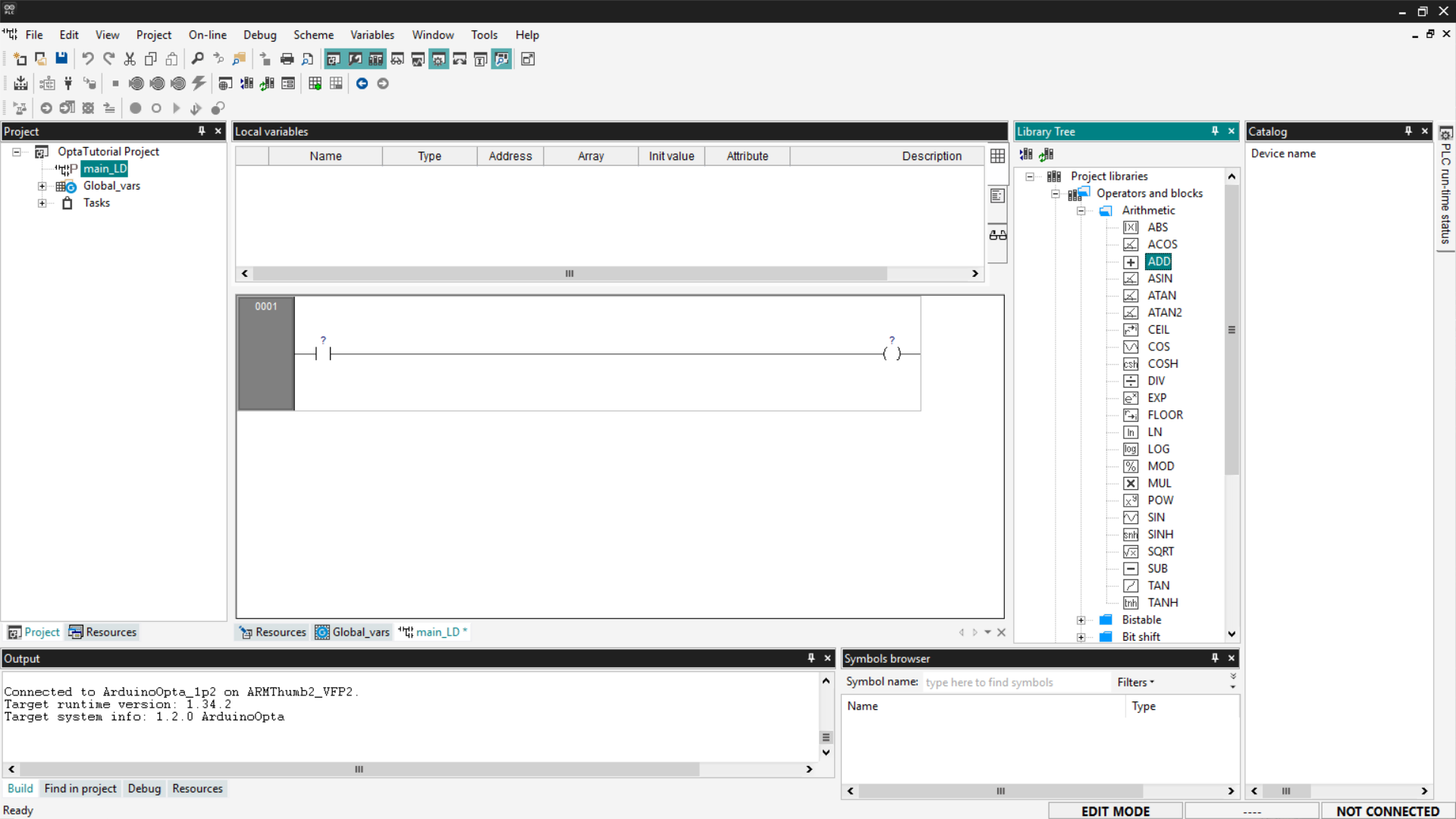
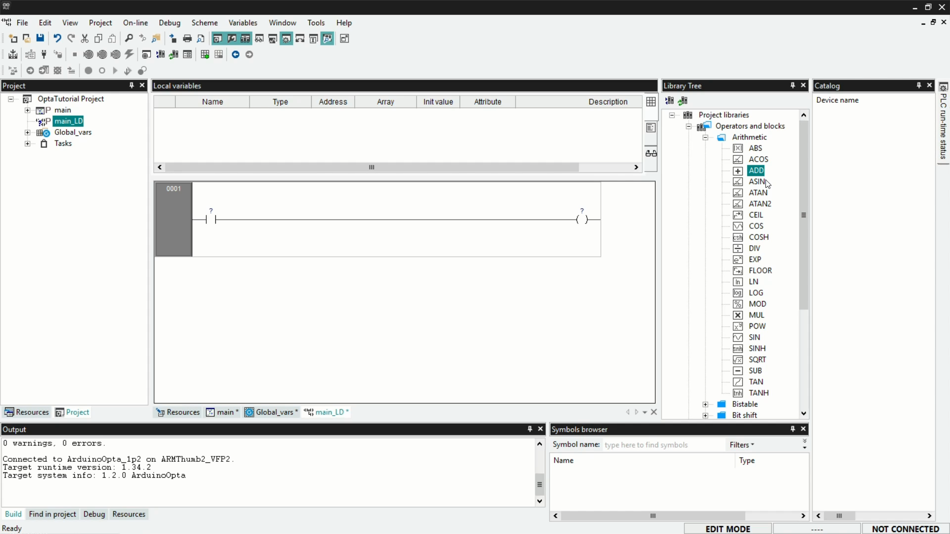
Now we need to add a logic block; to do this, go to the Library Tree section. If you don't see it, click View > Tool Windows > Library Tree. Click on Operators and blocks, then on Arithmetic, and you will see various types of logic blocks.
To add a block to your program, click on the desired block name (ADD in our case) and drag it onto the contact component on the left in the program. Alternatively, you can right-click and select New Block, filter by Operators, and select the ADD block from the list.
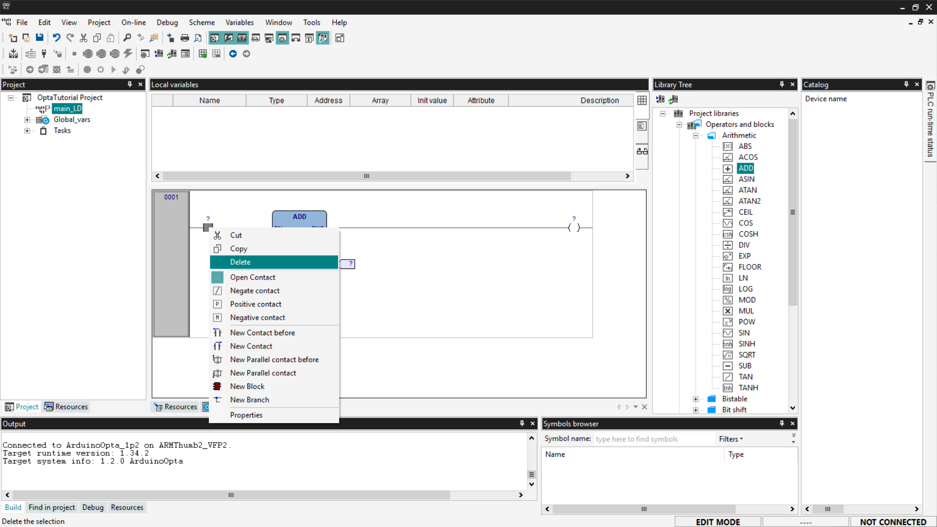
Once the block is added, delete the contact and coil components by right-clicking on them and selecting Delete; as mentioned before, they are not needed for our example.
At this point, you need to associate the variables with the function block pins. For the ADD block, the input variables are on the left side of the block, and the output variable is on the right side. To connect the variables to the pins, click on the desired pin; a window will open with a Browse button indicated by three dots.
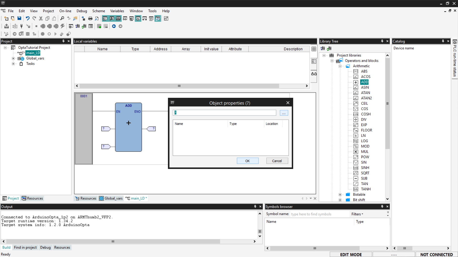
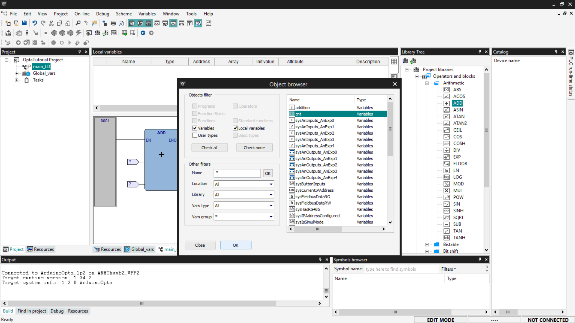
From the list, choose the variable to associate with the selected pin.
Once the association is complete, your LD program should look like the screenshot below. Remember to associate cnt and addition as inputs and cnt again as the output.
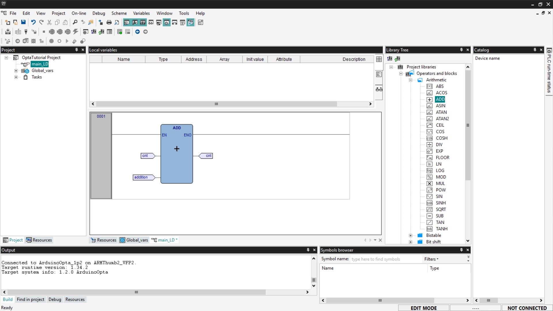
Save the project.
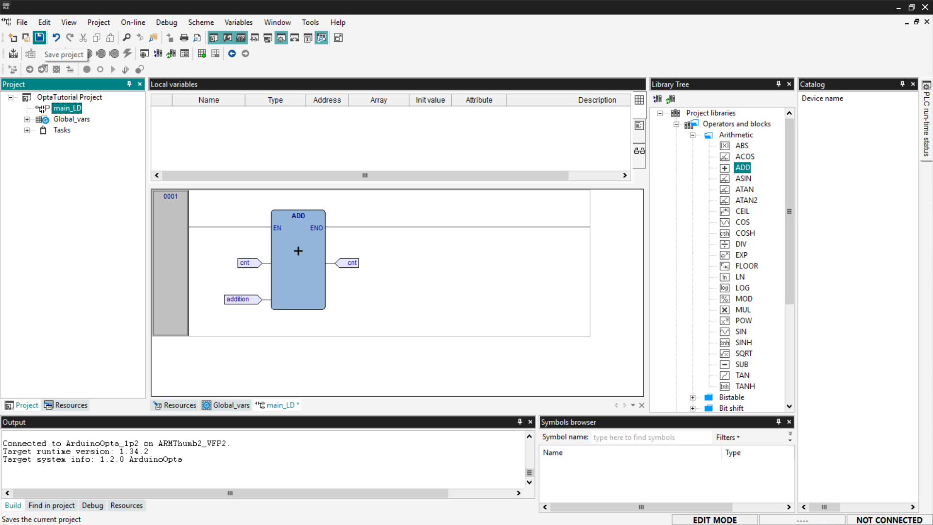
Proceed to compile the program by clicking the Compile PLC project button at the top left.
Connect to Finder OPTA and download the code to the PLC by clicking Download PLC code.
Open the Watch and monitor the value of the cnt variable.
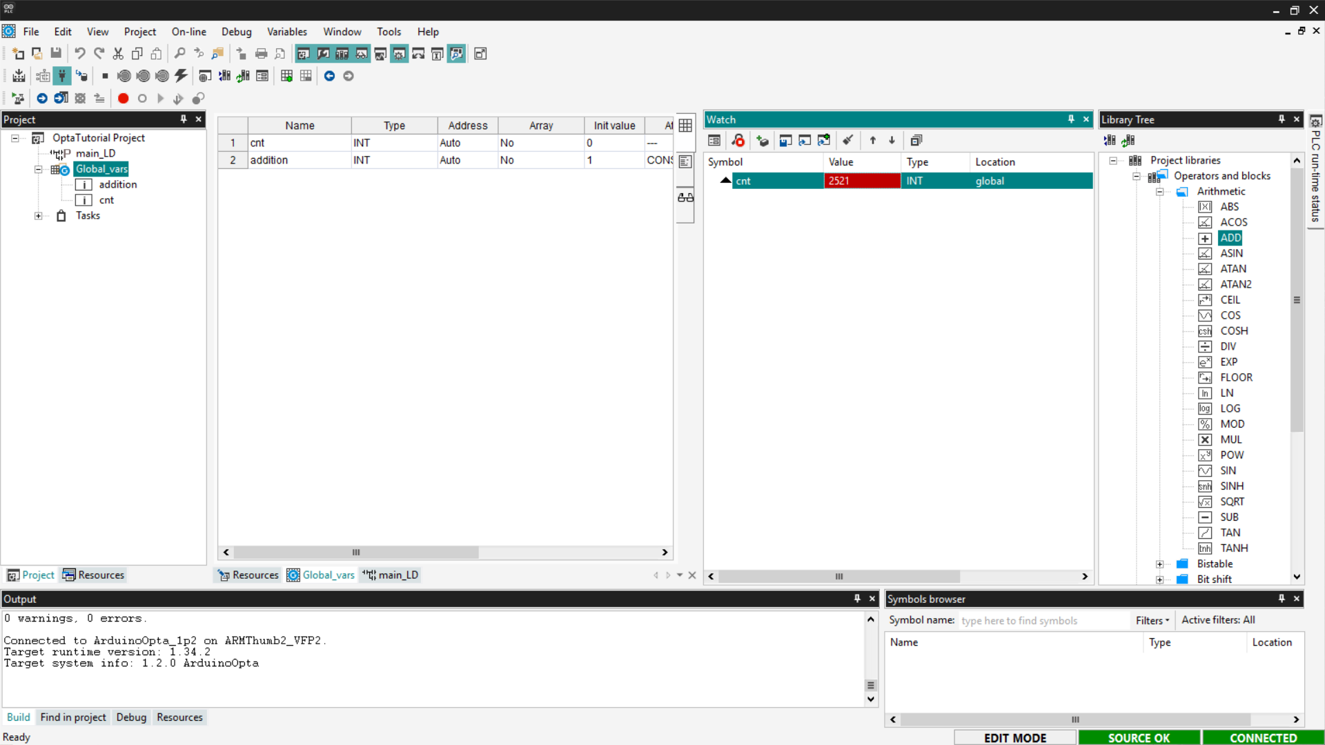
If the counter updates as expected, the LD program has been loaded and executed correctly on Finder OPTA.
Sequential Function Chart (SFC)
SFC is a language that allows writing PLC programs visually, following a flowchart-like logic. SFC programs are composed of blocks that perform specific operations, followed by transitions that determine when to move to the next step.
It is important to note that the SFC language cannot interact directly with the device’s outputs. To control the outputs, actions must be used, which are scripts written in other languages.
In this section, we will see how to write a counter in SFC. First, delete the previously created programs and add a new one by setting the language to SFC and assigning it to the Fast task.
Creating an Action
An action is a block of code written in another language—such as ST—that is executed when triggered by a step in the SFC diagram.
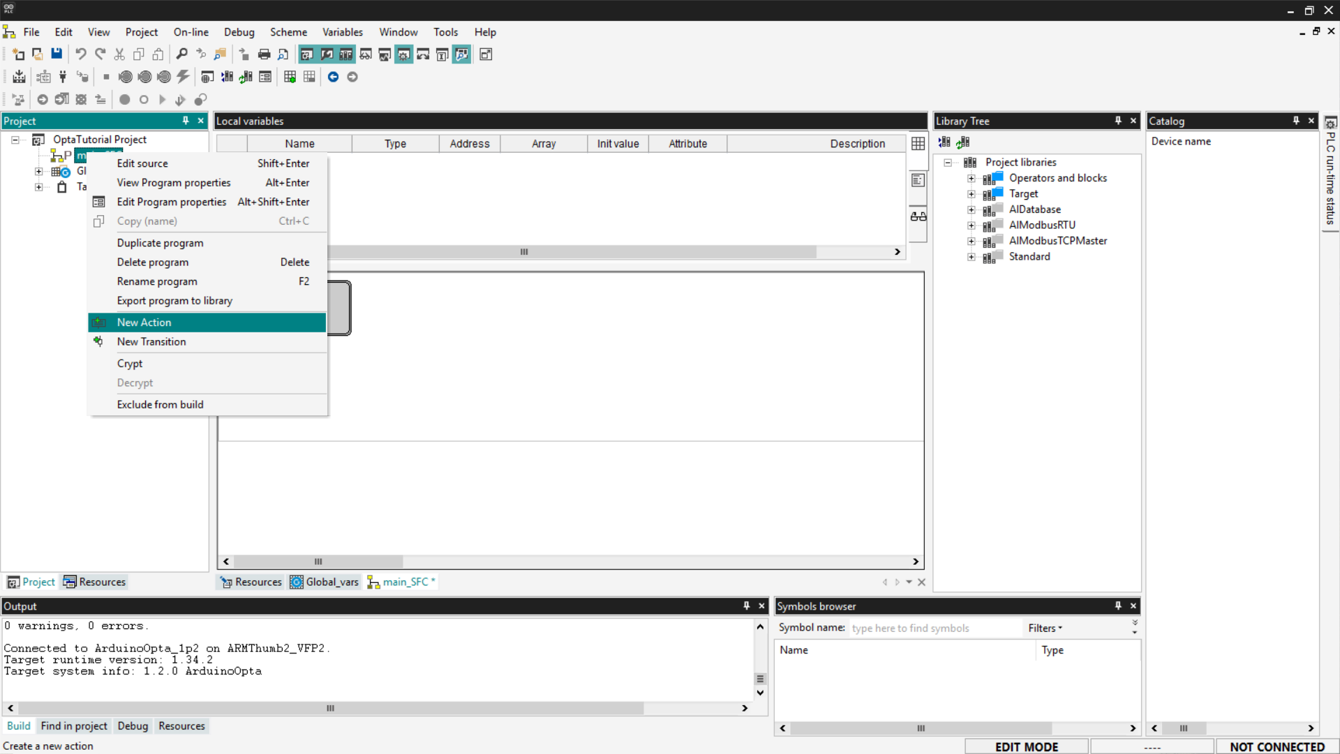
To create a new action, right-click on the new program entry and select New Action.
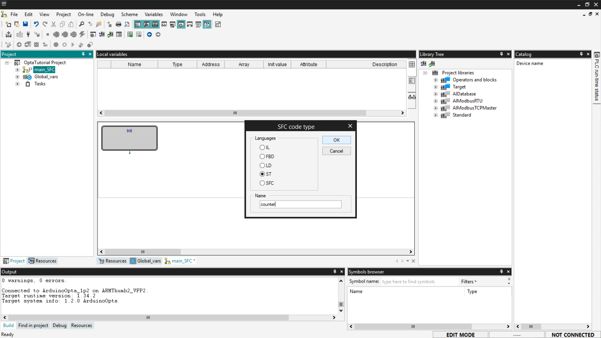
At this point, select the language of interest—in our case, we will use ST—and name the new action.
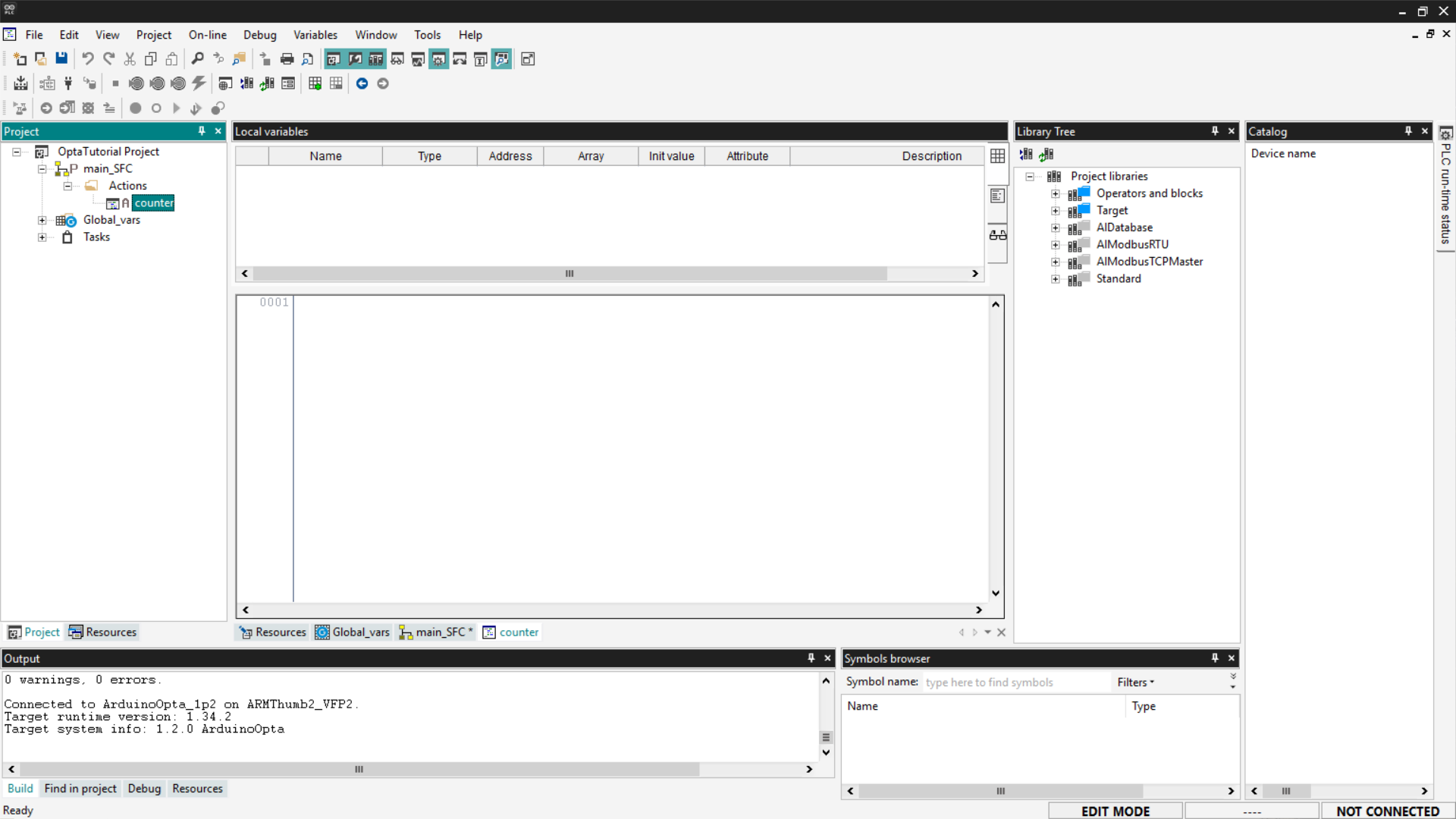
To access the code of the newly created action, navigate to the SFC program entry in the menu, expand the Actions entry, and click on the action name.
This way, you can insert the ST code you prefer; for our example, we will insert the same code we saw previously in the ST language section. Copy the following code and insert it into the program as shown in the image.
cnt := cnt + addition;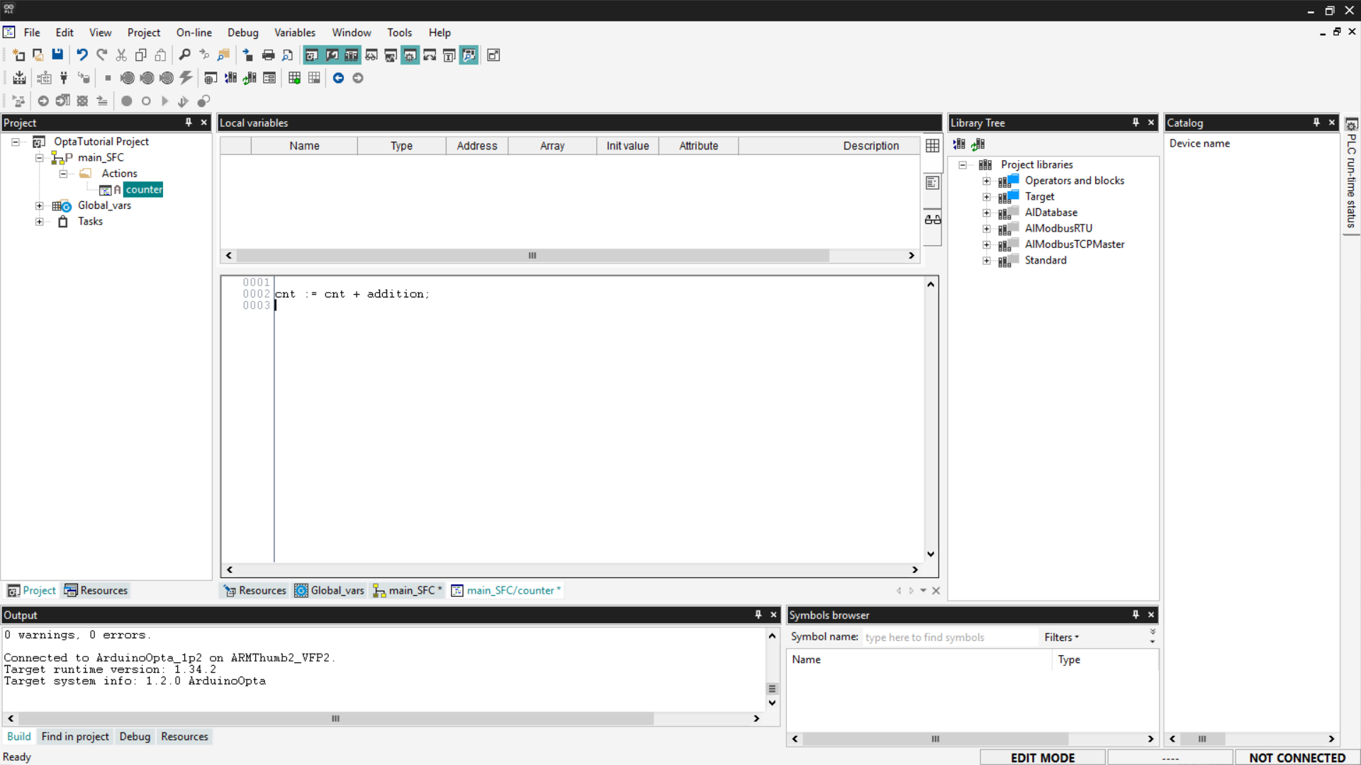
After inserting it, save the project.
SFC Program
An SFC program follows a precise sequence:
Step0 → Transition0 → Step1 → Transition1 → … → Jump- A Step represents an action to be executed.
- A Transition indicates when to move to the next step based on the result of the previous action.
- A Jump is used to connect to another step in the diagram. If you want to create a loop, use a Jump to return to the initial step called Init.
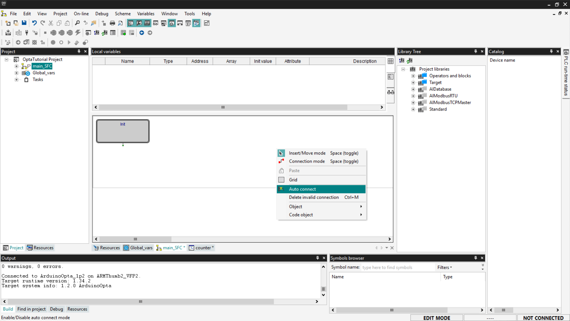
Before starting, right-click and ensure that the Auto-connect option is enabled. This function allows you to automatically connect blocks after adding them.
To add a transition, right-click and select Object > New > Transition. Alternatively, you can use the SFC toolbar, which is shown by selecting View > Toolbar > SFC.
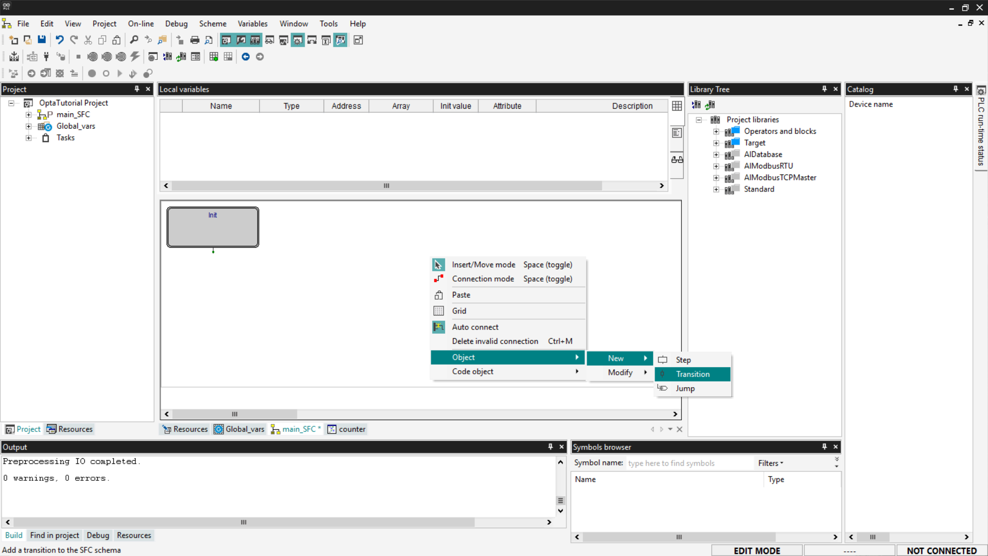
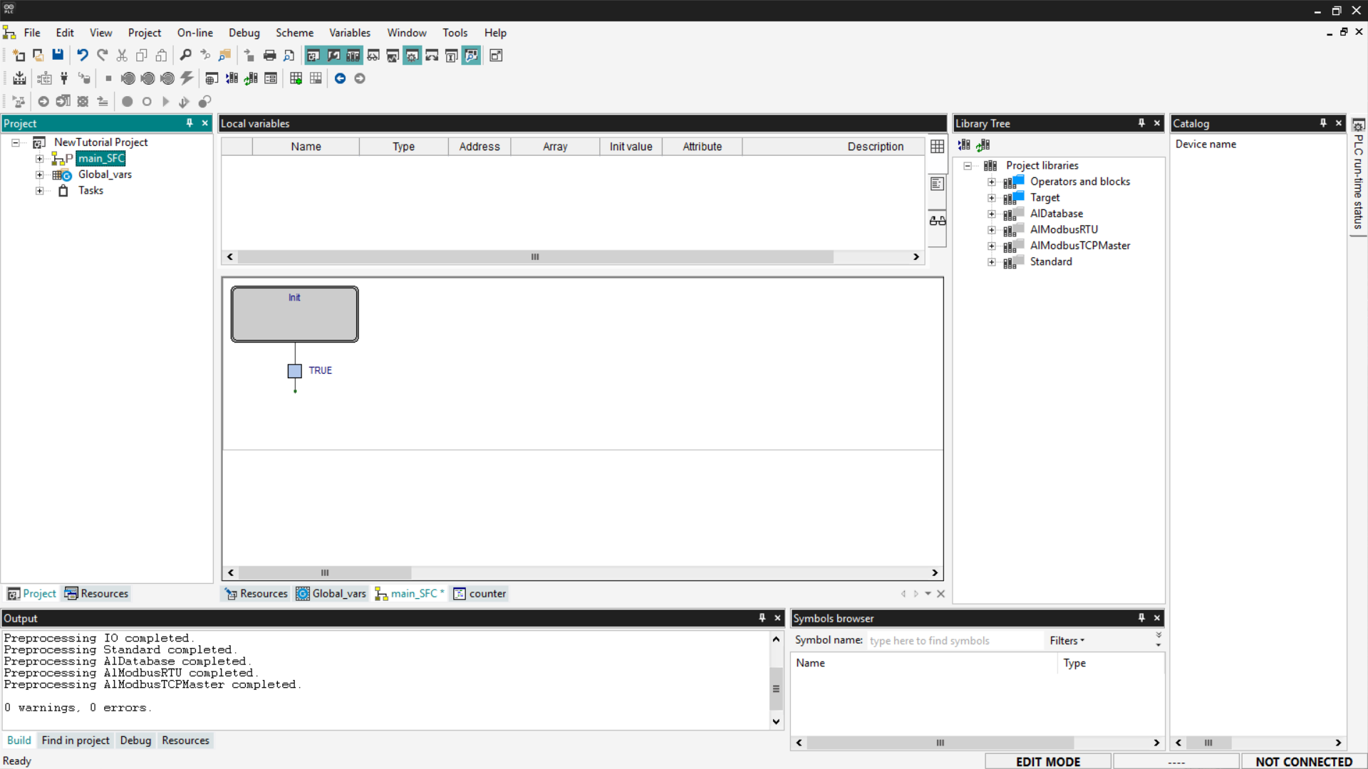
Connect the transition to the output of the Init block. Transitions are required after each Step block; for our example, a simple transition set to True is sufficient.
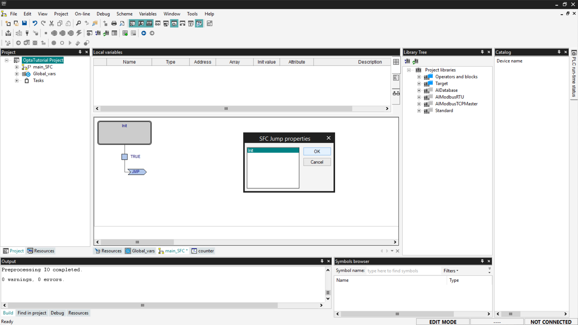
Now add a Jump block; this block allows you to reconnect the flow to an already existing block.
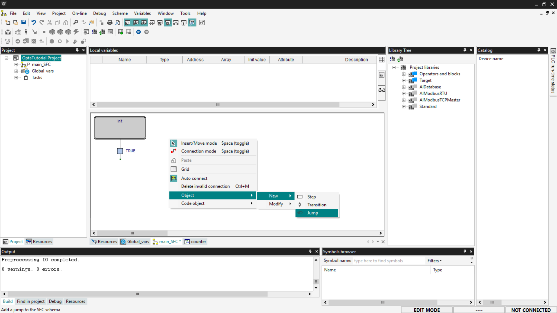
Associate the new block with the Init block to allow the program to start over again.
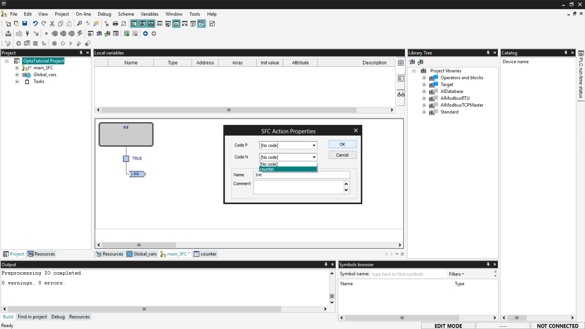
In action blocks, you can set two execution modes:
- Code P (Pulse): the action is executed only once each time the block is activated.
- Code N (Normal not stored): the action is executed continuously, on every PLC cycle, as long as the block remains active.
In our example, we will use Code N, so we can observe the constant increment of the cnt value. To set this mode, select the Init block, add or modify the action, and assign Code N to it.
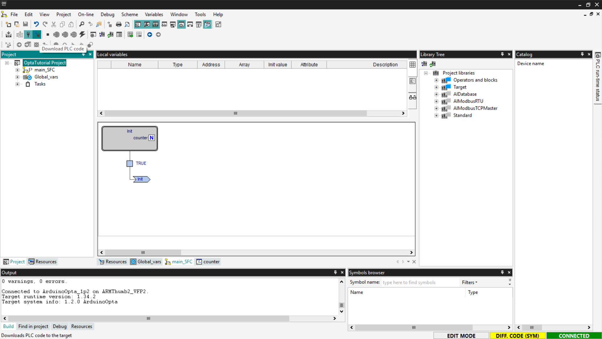
At this point, save, compile the project, connect to Finder OPTA, and download the code to the PLC using Download PLC code.
Open the Watch and start monitoring the cnt variable.
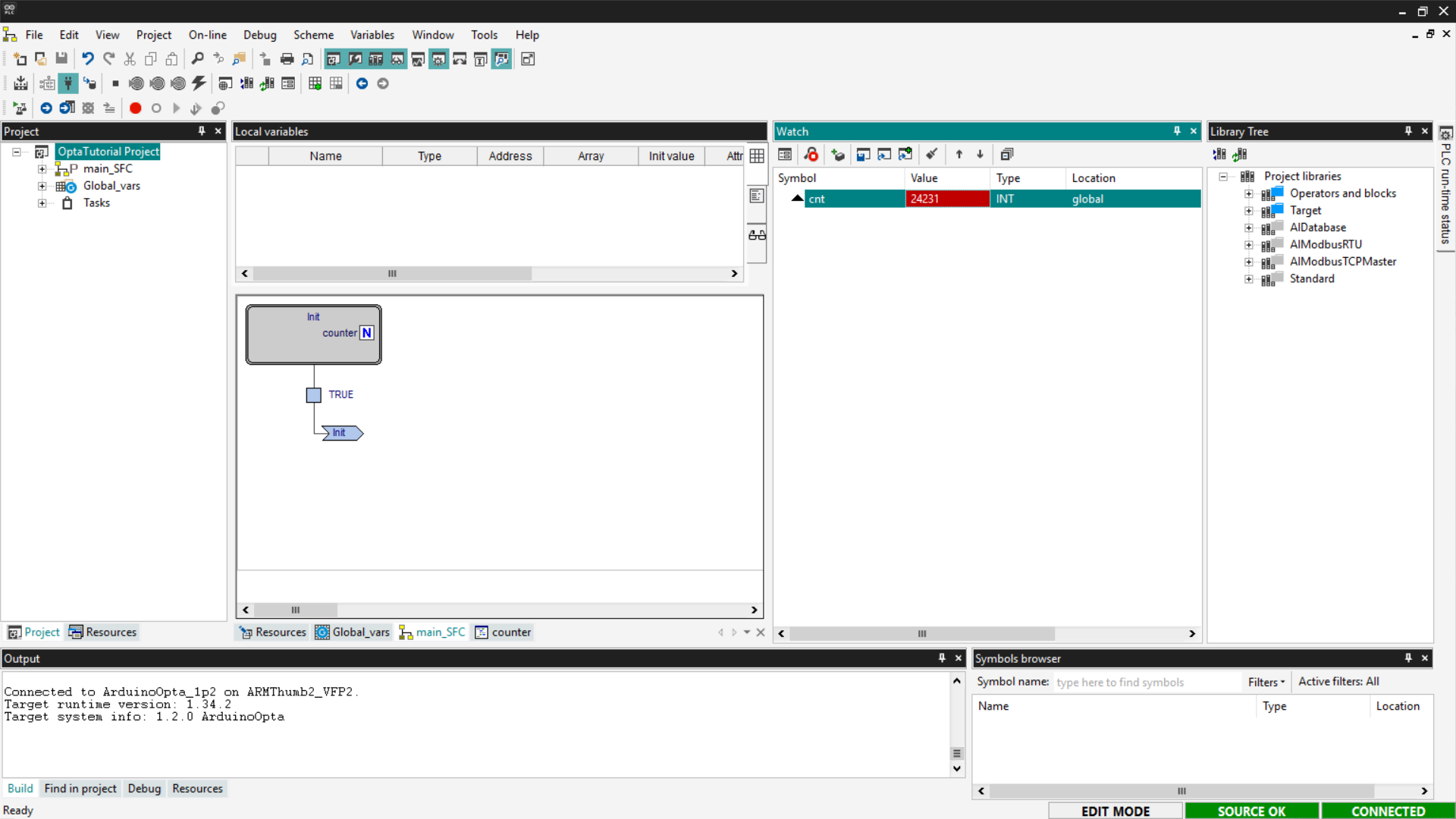
If the counter updates as expected, the SFC program has been loaded and executed correctly on Finder OPTA.
Functional Block Diagram (FBD)
FBD is a language that allows writing PLC programs using a graphical representation based on function blocks. In FBD, there is no rigid sequential flow: blocks are executed simultaneously on each PLC scan cycle, based on the connections between inputs and outputs.
Each block represents a specific logical or mathematical function. For example,
by adding an Add block, the addition operation is performed on each execution
cycle.
To implement a counter in FBD is very simple. Start by deleting the programs created in previous steps and adding a new one to the project by selecting the FBD language and assigning it to a Fast task.
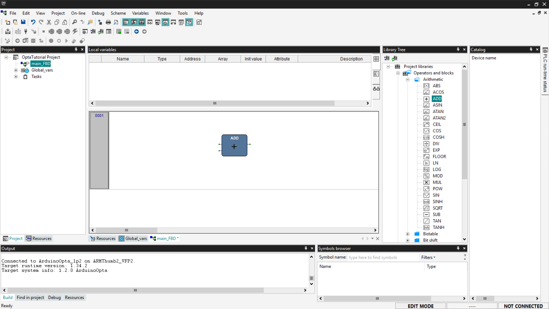
At this point, the steps are very similar to those seen in the Ladder Diagram section. Add an ADD block by dragging it from the Library Tree section or by using the right-click menu.
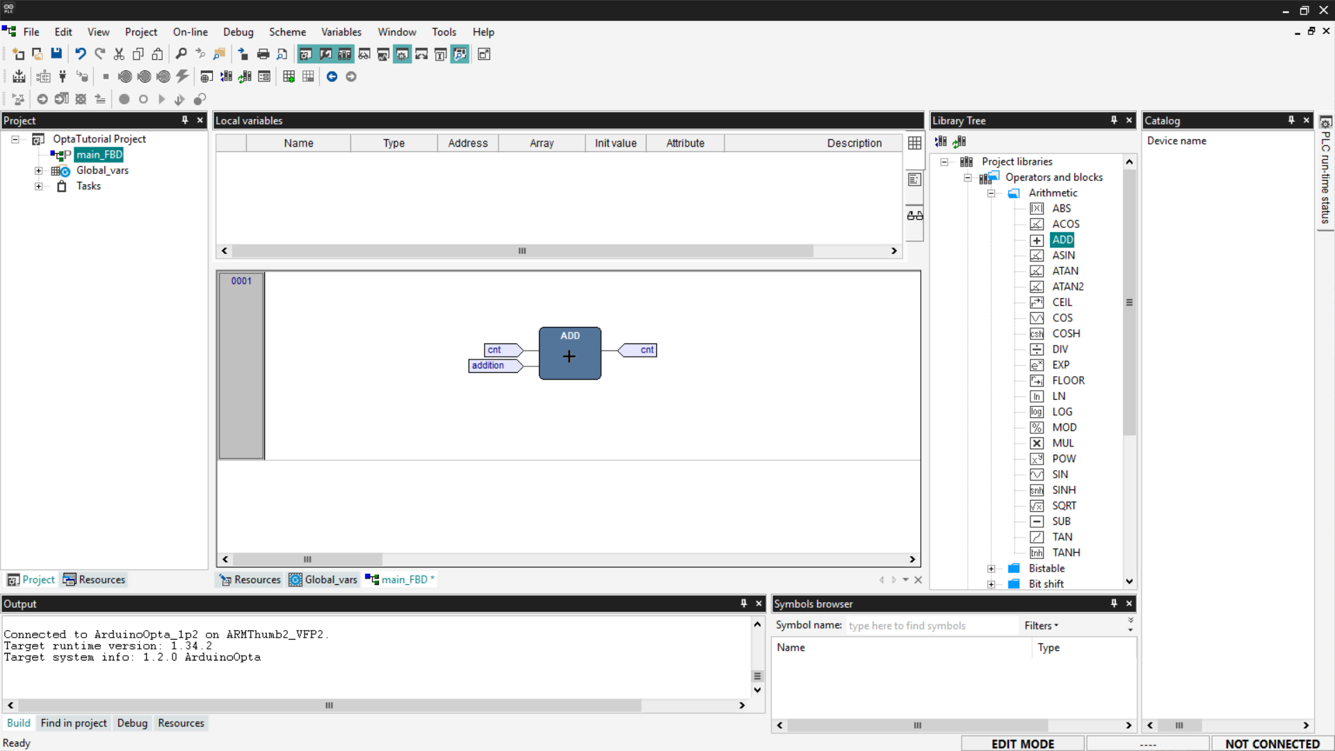
Associate the variables of interest as seen previously: inputs cnt and addition on the left side of the block, output cnt on the right side of the block. To do this, simply double-click on the block connectors. Once configured, the pins will appear as shown below.
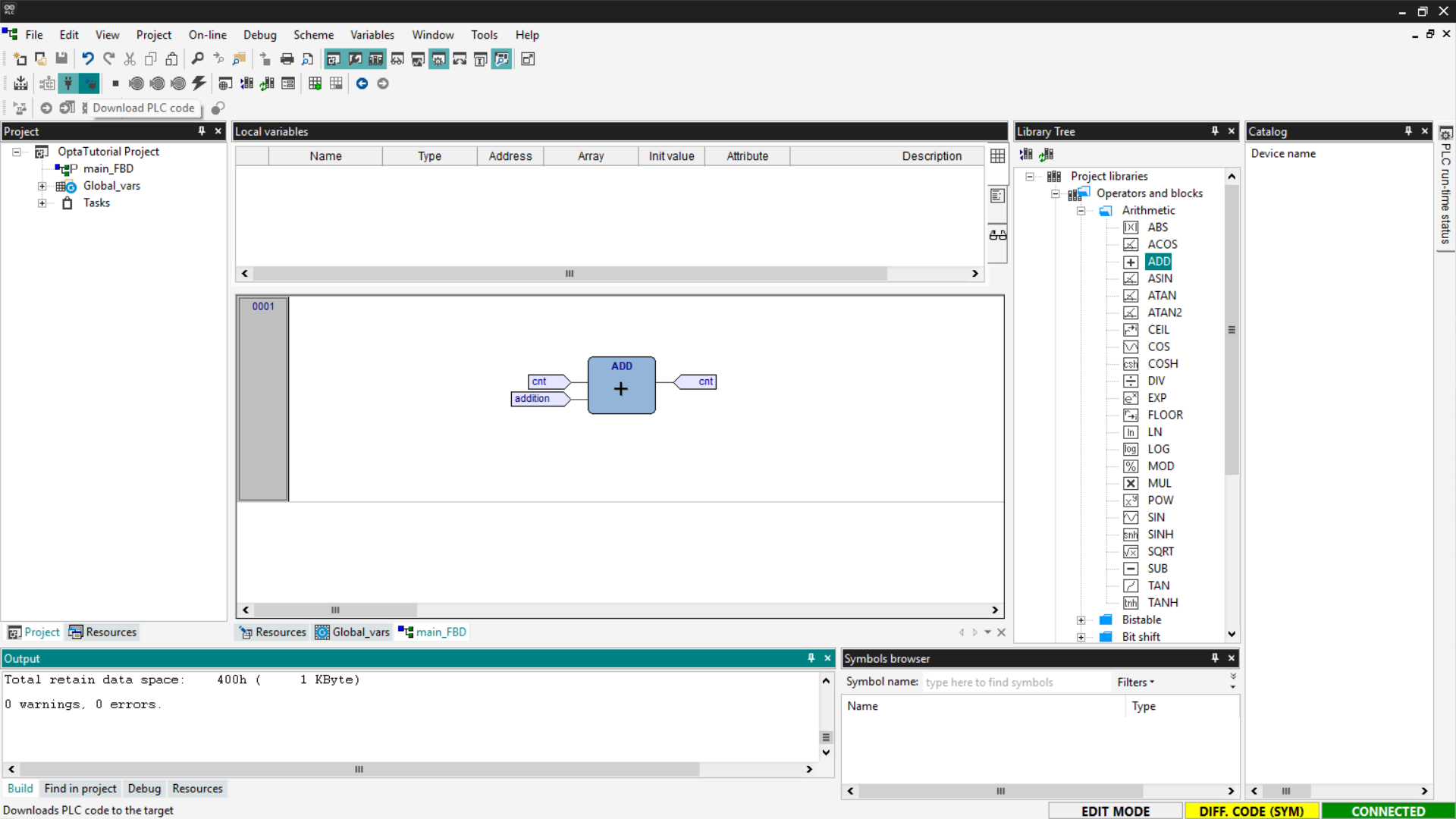
Now save, compile the project, connect to Finder OPTA, and download the code to the PLC using Download PLC code.
Open the Watch and start monitoring the cnt variable.
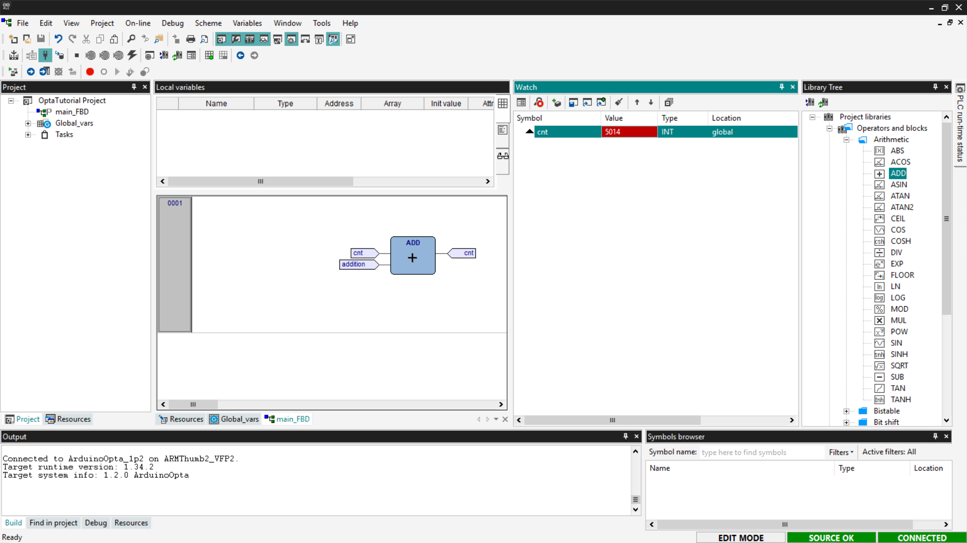
If the counter updates as expected, the FBD program has been loaded and executed correctly on Finder OPTA.
Integration with Arduino Sketches
In addition to standard languages, PLC IDE allows integrating Arduino sketches, enabling the combination of PLC programming with C++ code. This integration occurs through shared variables, which allow communication between IEC-61131-3 code and Arduino sketches.
This way, it is possible, for example, to reuse existing PLC logic and enhance it with C++ code to implement advanced features. This approach allows expanding an existing system without having to redesign the basic logic.
In this section, we will see how to make an Arduino sketch communicate with an ST program. We will write a counter in C++ that communicates with the ST code so that we can verify that the variable updates correctly.
Delete the previously written programs, create a new one in ST language and assign it to a Fast task. It is necessary to add a shared variable that can be accessed by both the sketch and the ST program. Shared variables are divided into two types:
- Input: input variables are used to pass a value from the PLC program to the sketch and are accessible with the prefix PLCIn.
- Output: output variables are used to pass a value from the sketch to the PLC program and are accessible with the prefix PLCOut.
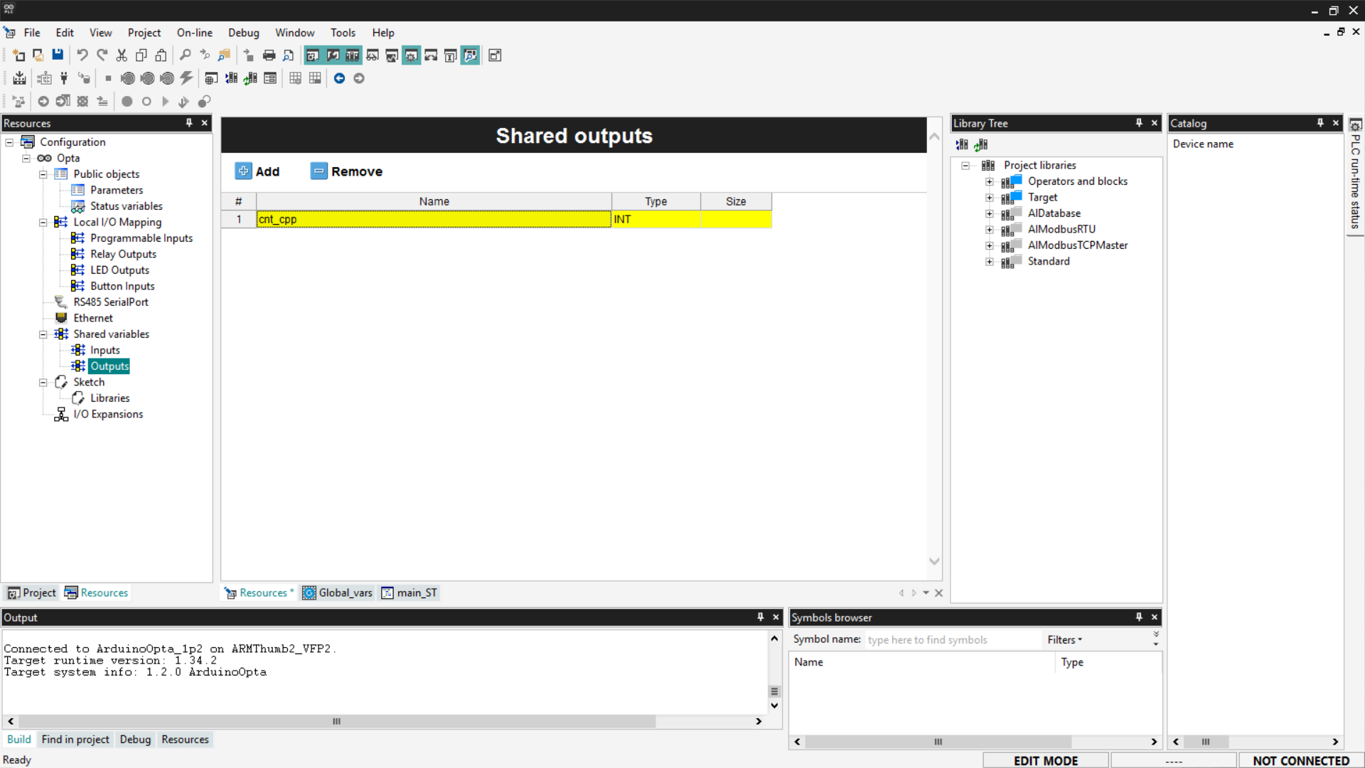
In this case, we will need to use an output variable that is updated by the sketch. To add an output variable, go to the Resources section, expand Shared variables, and select the Outputs entry. A blank list will appear; click the Add button and rename the newly added variable as follows.
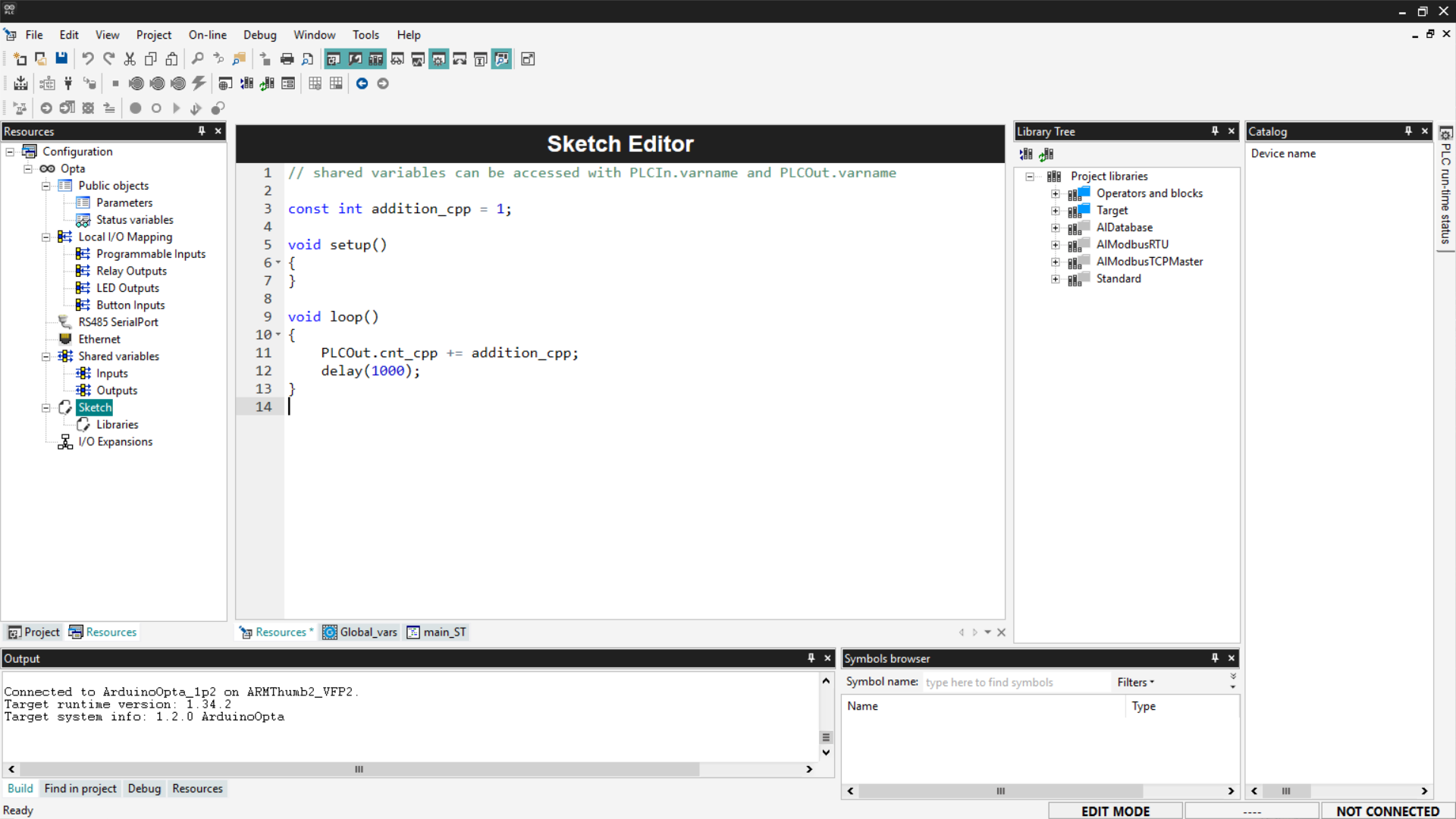
Now let's write the C++ code that implements the counter logic. First, define a constant variable — addition_cpp — used as the increment. Inside the loop() function, update the shared variable cnt_cpp by adding the value of addition_cpp each cycle. Remember that shared output variables are accessible from the sketch via the PLCOut prefix. Also, include a 1-second delay in the loop, so that the increment of the variable is easily observable during monitoring.
Copy the code below and paste it into the Sketch page under the Resources section.
const int addition_cpp = 1;

void setup()
{
}

void loop()
{
    PLCOut.cnt_cpp += addition_cpp;
    delay(1000);
}
At this point, all you need to do is write a simple ST program that replaces the value of the global variable cnt with the updated value of cnt_cpp. Below is the code to paste into the program, following the procedure indicated in the ST language section.
cnt := cnt_cpp;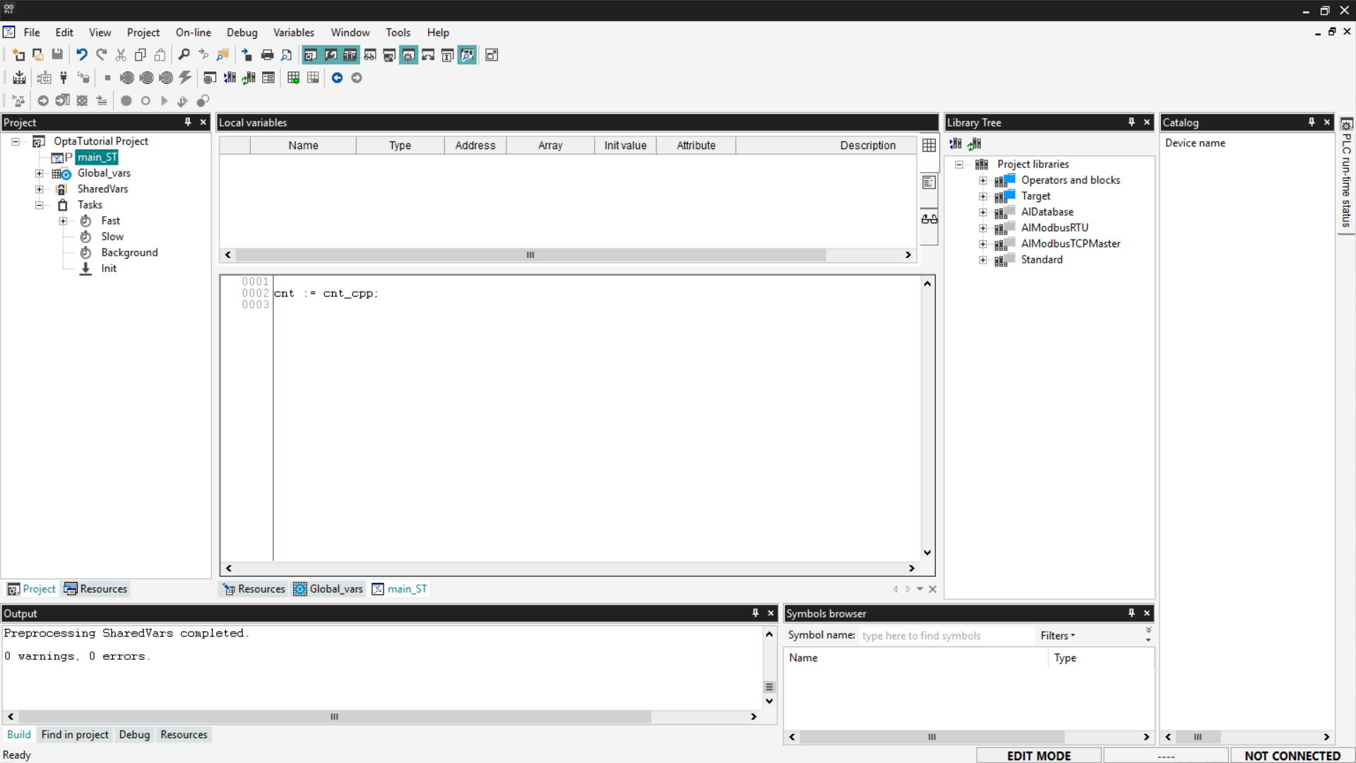
Save the project, compile it, connect to Finder OPTA, and download the code to the PLC. Then open the Watch and start monitoring the cnt variable.
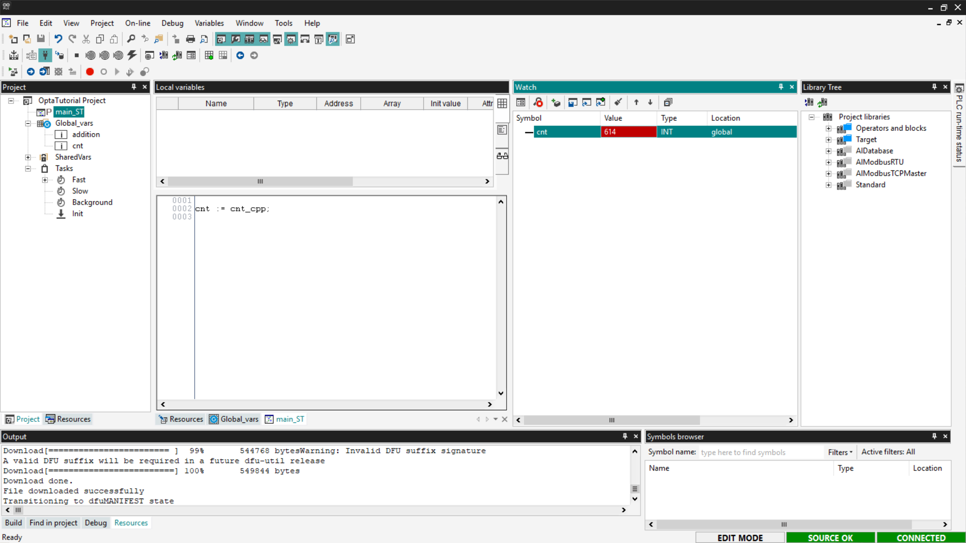
If the counter updates as expected, the sketch has been loaded and communicates correctly with the ST program.
Adding a Library to the Sketch
As mentioned earlier, PLC IDE allows combining PLC programming with C++ code.
If you want to add a library to the sketch, go to the Resources tab and click on Libraries under the Sketch entry.
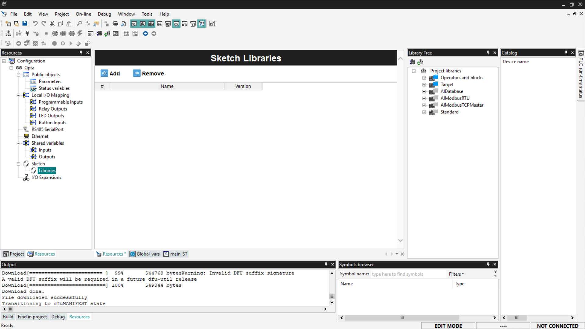
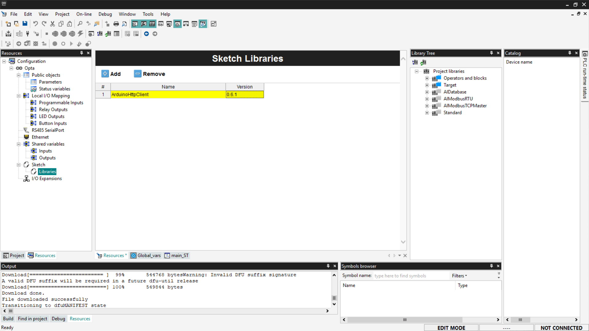
With the Sketch Libraries window open, click Add, and a new row will be added to the list. Enter the library name and version manually, which can be found in the library’s documentation. In this example, we add the ArduinoHttpClient library; the version number and its documentation can be found at this link.
Once the library is added to the project, simply include it in the code by clicking on the Sketch entry in the Resources menu and inserting the following line at the top of the code:
#include <ArduinoHttpClient.h>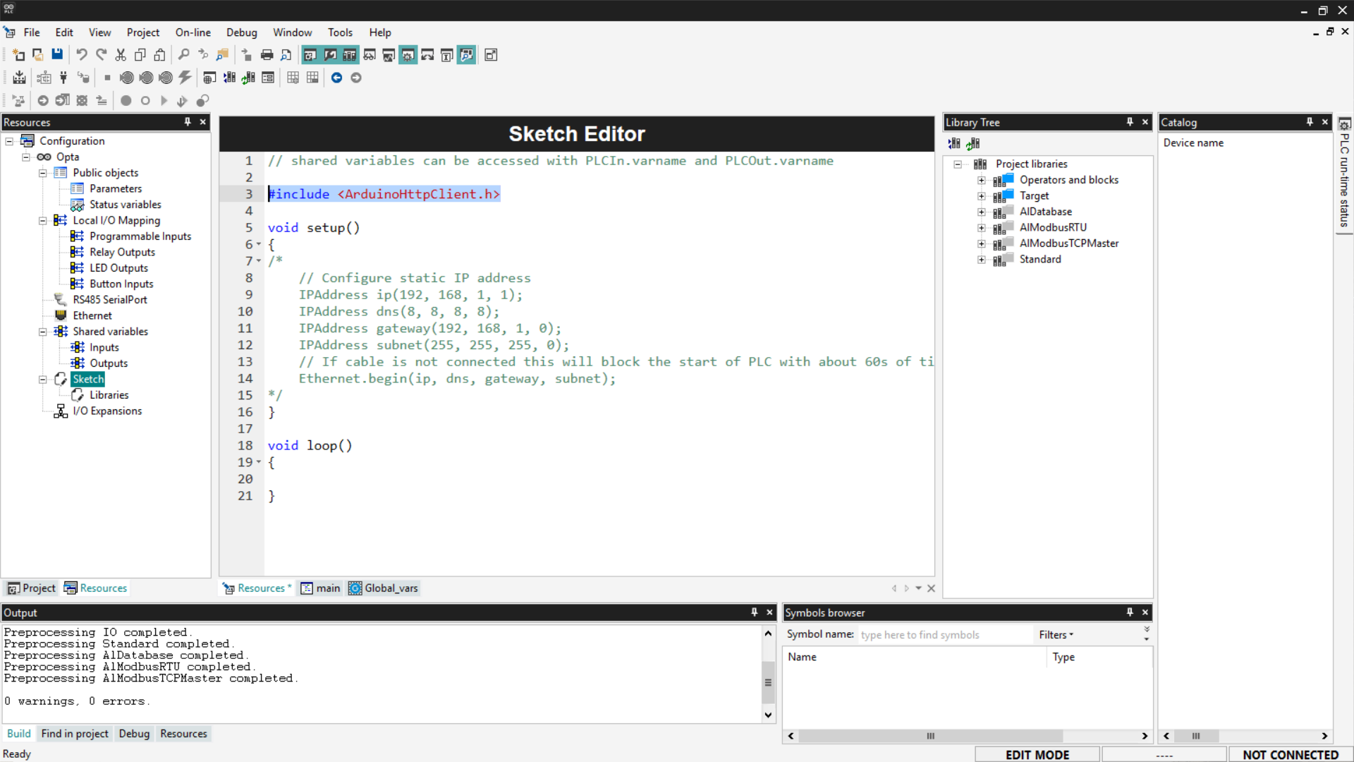
In this way, the library is usable throughout the sketch code.
Note: currently, PLC IDE can only include libraries publicly indexed on the Arduino website.
Conclusion
In this tutorial, we explored the capabilities of Arduino PLC IDE with Finder OPTA, showing how to configure global variables and create sample programs in the five IEC-61131-3 languages (ST, IL, LD, SFC, and FBD). We also demonstrated how to integrate an Arduino C++ sketch via shared variables, thereby extending the PLC’s functionality with C++ code.